
Stack type battery

a stack type, battery technology, applied in the direction of cell components, sustainable manufacturing/processing, final product manufacturing, etc., can solve the problems of creases and warpages in the battery case, easy formation of gaps between the electrode assembly and the battery case, and poor welding ability of the welded portions between the metal foils and the metal plate, so as to effectively prevent the construction of a stack type battery

Inactive Publication Date: 2011-10-06
SANYO ELECTRIC CO LTD
View PDF3 Cites 35 Cited by
  • Summary
  • Abstract
  • Description
  • Claims
  • Application Information

AI Technical Summary

Benefits of technology

[0010]It is an object of the present invention to provide a stack type battery that can effectively prevent creases or warpage formed in the battery case during vacuum-sealing in the case that the battery is constructed using a battery case having flexibility.
[0016]a battery case having flexibility and accommodating the stacked electrode assembly therein; and
[0021]a battery case having flexibility and accommodating the stacked electrode assembly therein; and
[0024]The present invention makes it possible to effectively prevent a stack type battery constructed using a battery case having flexibility from creases or warpage formed in the battery case during vacuum-sealing.

Problems solved by technology

In this process, a gap tends to form easily between the electrode assembly and the battery case, particularly at the portion from which the current collectors protrude, and at the location where the gap is formed, creases and warpage tend to form in the battery case because of the internal pressure change resulting from the evacuation.
However, in this case, weldability of the welded portions between the metal foils and the metal plate tends to be poorer than that of the welded portions of the metal foils to each other, because of their thickness difference.
When the weldability becomes poor, the connection resistance between each of the electrode plates and the current collector terminal becomes non-uniform, causing variations in the current values flowing into the respective electrode plates especially when used at high rate.
As a consequence, uneven charge-discharge states arise in the battery, causing overdischarge and overcharge partially.
Consequently, the cycle performance of the battery deteriorates.
However, when the above-described two-stage connection structure is employed, a portion in which only the electrode plate lead tabs are joined needs to be provided between the current collector terminals and the electrode plates, and correspondingly, the length of the electrode plate lead tabs inevitably becomes long.
As a consequence, creases in the battery case develop at that position.

Method used


Image

  • Stack type battery
  • Stack type battery
  • Stack type battery

Examples


example 1

[0079]A stack type battery fabricated in the same manner as described in the foregoing embodiment was used as the stack type battery of this example.

[0080]The battery fabricated in this manner is hereinafter referred to as Battery A1 of the invention.

[0081]In the following examples and the drawings, parts and components that are or similar to those described in the foregoing embodiment and Example 1 above as well as in FIGS. 1 through 11 are denoted by like reference numerals and symbols, and no further details thereof are given unless necessary.

example 2

[0082]As illustrated in FIG. 12, a first spacer 56 and a second spacer 55 were individually formed so as to have the same configurations as the first cover portion 52 and the second cover portion 51, respectively, of the integral-type spacer 5 in Battery A1 of the invention. The first spacer 56 and the second spacer 55 are laterally long members having the same cross-sectional shape as each other. Needless to say, neither of the first spacer 56 and the second spacer 55 has a part that corresponds to the connecting piece 53 of the integral-type spacer 5 in Battery A1 of the invention. A stack type battery was fabricated in the same manner as the foregoing Battery A1 of the invention, except that the first spacer 56 and the second spacer 55 were individually disposed at the same locations as the first cover portion 52 and the second cover portion 51 were disposed in the integral-type spacer 5 of Battery A1 of the invention.

[0083]The battery fabricated in this manner is hereinafter ref...

example 3

[0098]A stack type battery was fabricated in the same manner as the foregoing Battery A2 of the invention, except that positive and negative electrode lead tabs 57 and 58 did not employ the two-stage connection structure, i.e., the positive and negative electrode lead tabs 57 and 58 were connected to positive and negative electrode current collector terminals 59 and 60 without being bent, and that the first spacer was not provided.

[0099]The battery fabricated in this manner is hereinafter referred to as Battery A3 of the invention.

[0100]In the just-described Battery A3 of the invention, it was observed that when the battery case 18 was vacuum-sealed in the process of filling the electrolyte solution and sealing the battery case, misalignment of the second spacer 55 occurred, causing small creases and slight warpage in the battery case 18. However, the second spacer 55 prevented the battery case 18 from being forced into or dented at the portion (the current collector-side end) furth...


PUM


Abstract

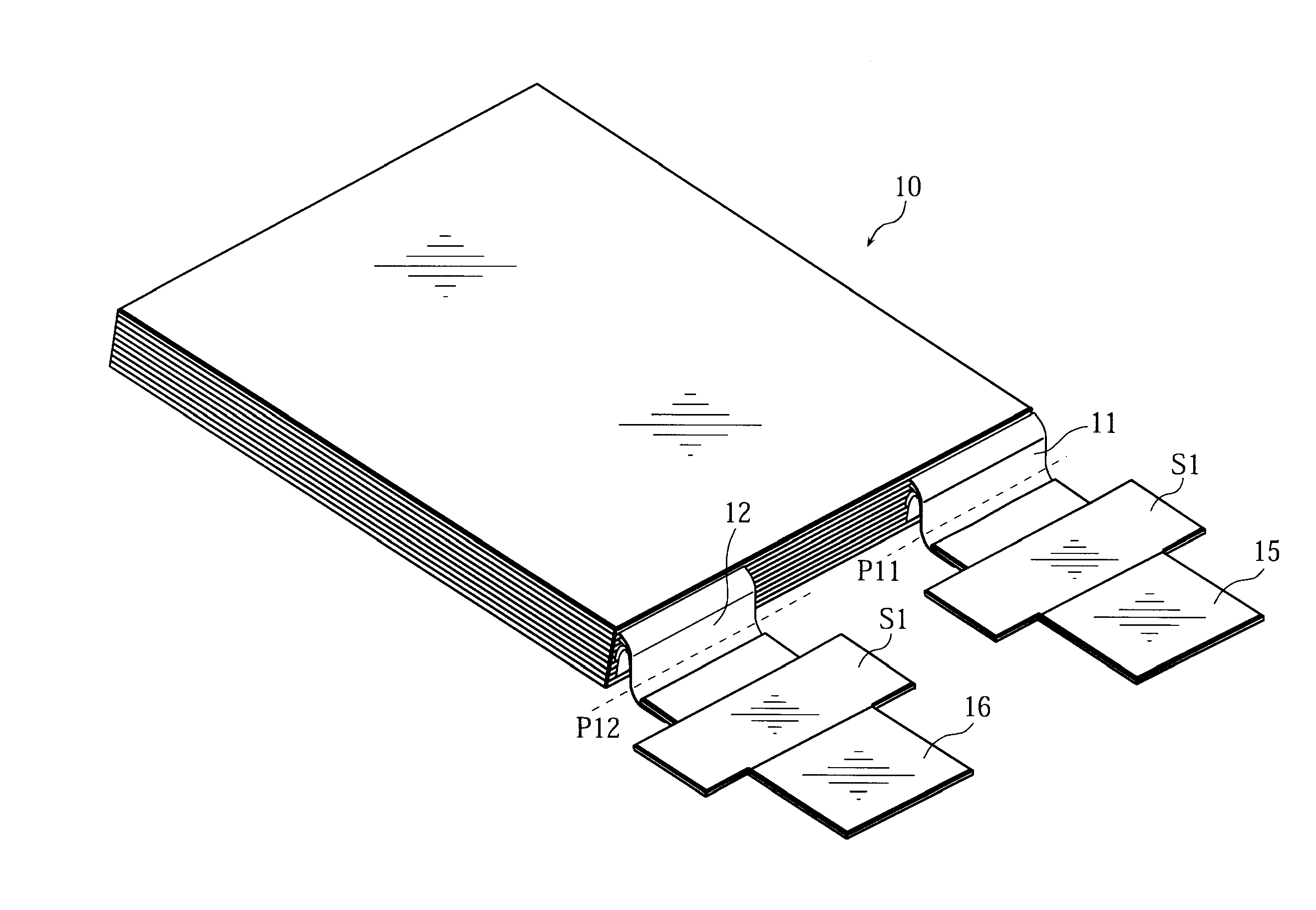
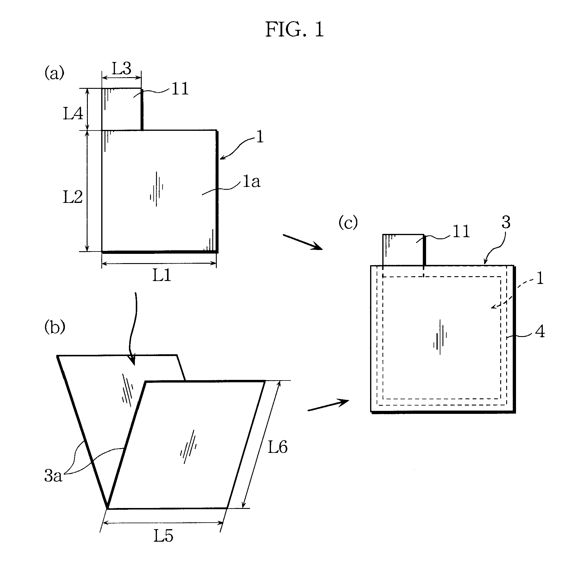
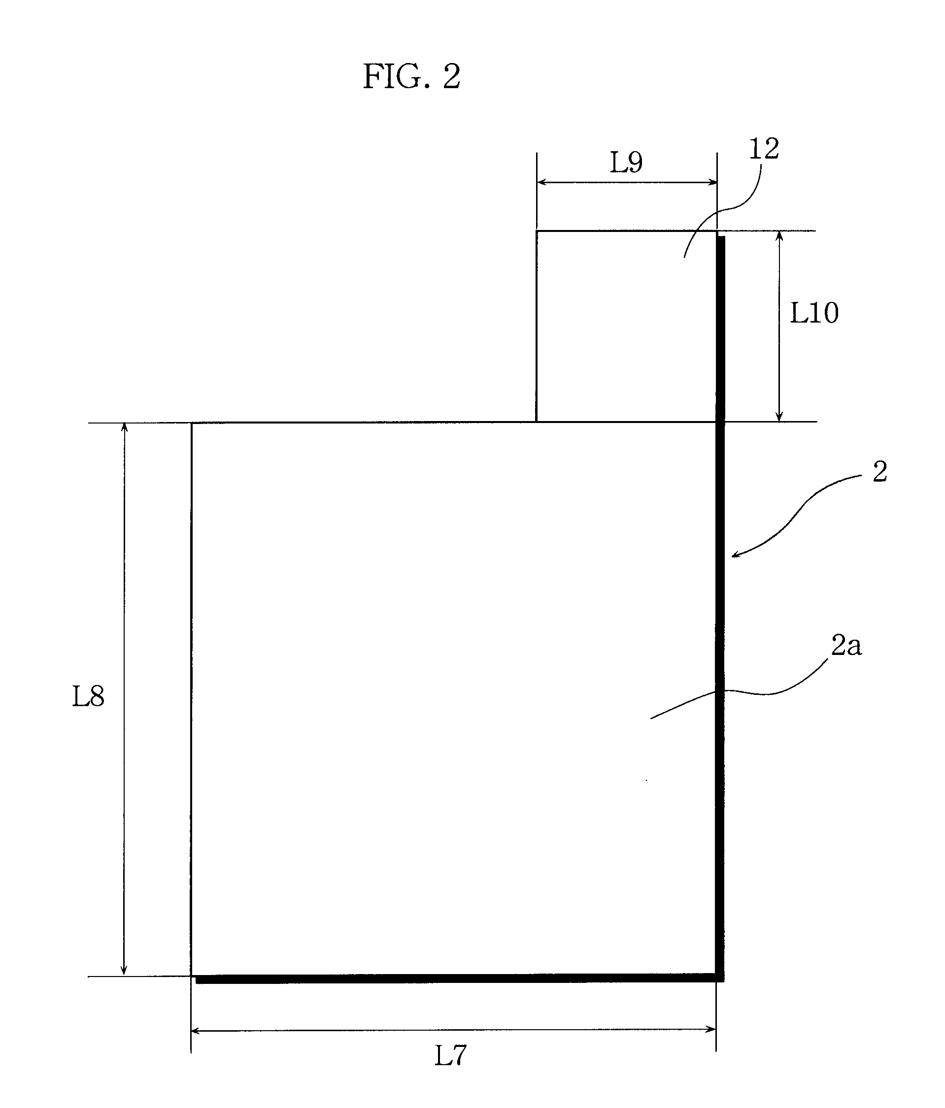
In a stack type battery, stacked positive and negative electrode lead tabs (11, 12) are joined to one another at a location between the current collector terminals and the electrode plates, the positive and negative electrode lead tabs (11, 12) being folded at an intermediate location between positive and negative electrode current collector terminals (15, 16) and positive and negative electrode plates and protruding from the positive and negative electrode plates. A stacked electrode assembly (10) is accommodated in a battery case (18) having flexibility. A first spacer (a first cover portion (52) of an integral-type spacer (5)) is disposed between the battery case (18) and an open side end of the positive and negative electrode lead tabs (11, 12) formed by folding the positive and negative electrode lead tabs (11, 12).

Description

BACKGROUND OF THE INVENTION[0001]1. Field of the Invention[0002]The present invention relates to stack type batteries used for, for example, robots, electric vehicles, and backup power sources. More particularly, the invention relates to a stack type battery that can accommodate the battery components in a compact manner and at the same time can inhibit the battery case from creases or warpage during vacuum-sealing.[0003]2. Description of Related Art[0004]When producing a stack type battery in which a stacked electrode assembly is accommodated in a laminate battery case having flexibility, it has conventionally been common practice to seal the battery case while evacuating the inside of the battery case (i.e., to perform vacuum-sealing), in order to infiltrate the electrolyte solution sufficiently into the electrode assembly. In this process, a gap tends to form easily between the electrode assembly and the battery case, particularly at the portion from which the current collectors ...

Claims


Application Information

Patent Timeline
IPC IPC(8): H01M2/00H01M4/02H01M10/04H01M50/528H01M50/536H01M50/54
CPCH01M2/26H01M2/266H01M10/0413Y02T10/7011H01M10/052H01M10/0585H01M10/0463Y02E60/10H01M50/54Y02P70/50H01M50/536H01M50/531H01M50/543H01M50/528H01M50/572
Inventor TANI, YUJIMAEDA, HITOSHISHINYASHIKI, YOSHITAKAFUJIWARA, MASAYUKIFUNAHASHI, ATSUHIRO
Owner SANYO ELECTRIC CO LTD
Learn More