Apnea monitor capable of measuring vital capacity

a monitor and vital capacity technology, applied in the direction of instruments, applications, force/torque/work measurement apparatus, etc., can solve the problems of too strong noise and too weak noise to detect, and achieve the effect of increasing the sensitivity of the apnea monitor and calculating the vital capacity

Inactive Publication Date: 2011-10-06
LU GUIXIAN
View PDF3 Cites 1 Cited by
  • Summary
  • Abstract
  • Description
  • Claims
  • Application Information

AI Technical Summary

Benefits of technology

[0003]The present invention directly measures breathing airflow instead of measuring the resistance of the chest. The objective of the present invention is to increase sensitivity of apnea monitor. Another objective is to measure vital capacity. The present invention collects parameters about breathing. Based on the parameters, vital capacity can be calculated. The parameters will also help in diagnoses.

Problems solved by technology

The reason that it does not give alarm when a baby stops breathing is that noise is too weak to detect.
The reason that alarm goes off when the baby is healthy is that the noise is too strong.

Method used


Image

  • Apnea monitor capable of measuring vital capacity
  • Apnea monitor capable of measuring vital capacity
  • Apnea monitor capable of measuring vital capacity

Examples


first embodiment

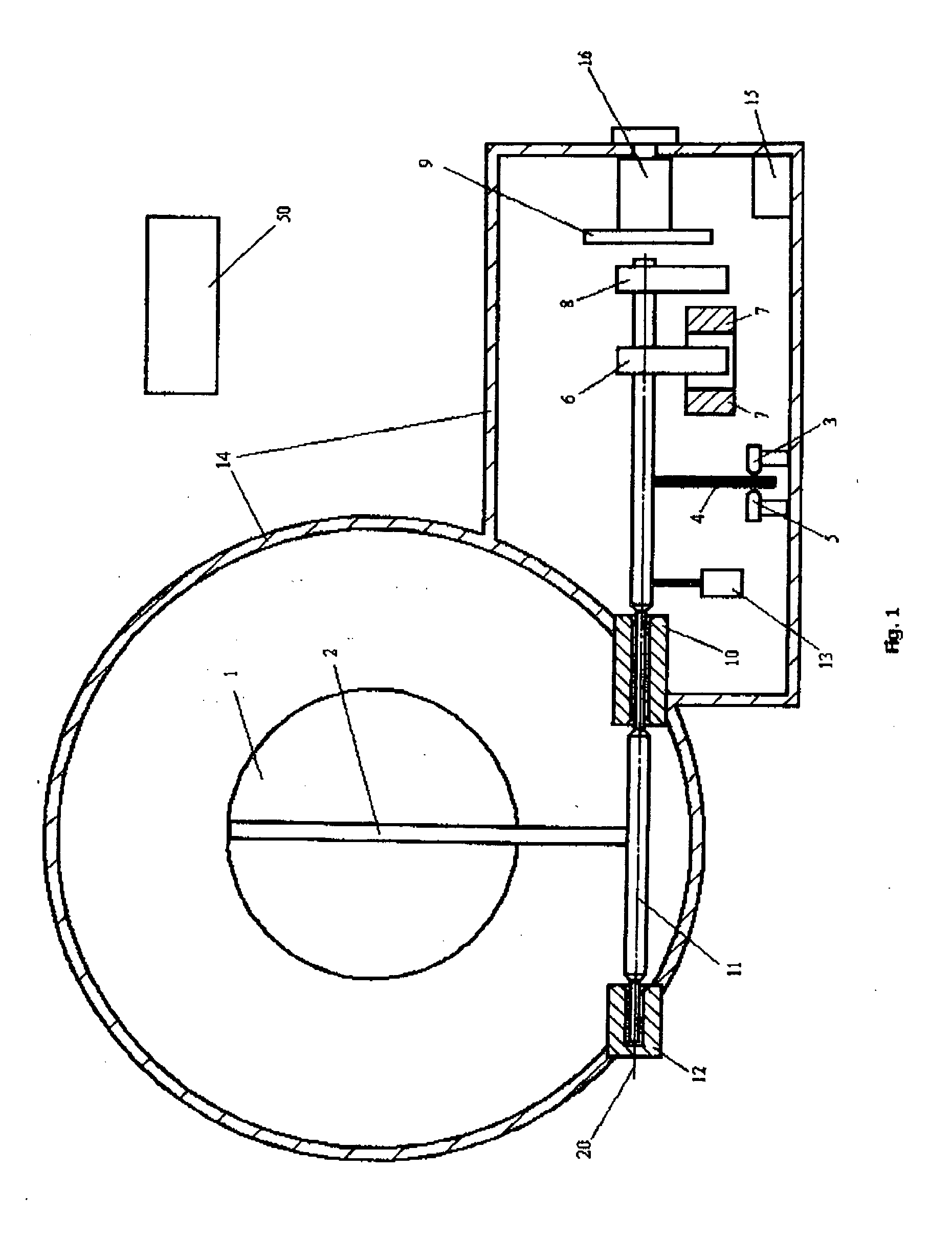
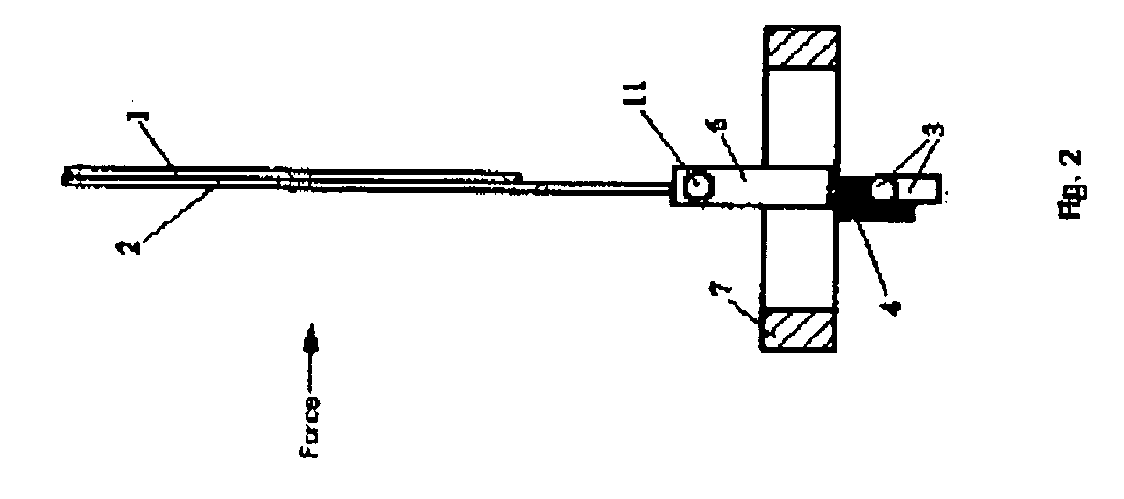
[0010]FIG. 1 and FIG. 2 show the first embodiment. Item 1 is a means of sensing pressure difference. When there is no difference of air pressure between two ends of the airflow sensor or no breathing, item 1 is in the original position, which is perpendicular as showed in FIG. 2. In this case every element in light sensor 5 is receiving maximum light from light source and has full output. The balance weight 13 is made so that the central weight of a rotating assembly is at or near the central line 16. The elements of the rotating assembly are item 1, item 2, item 4, item 11, item 13, item 6, and item 8. When pressure on the left (see FIG. 2) of air flow sensor is greater than pressure on the right of the air flow sensor, item 1 generates torque around axle 11 to clockwise (see FIG. 2) rotate the assembly. Elements of means of measuring position are light source 3, light sensor 5, and light path controller 4. The further the item 1 has gone to the right the light path controller 4 bl...

second embodiment

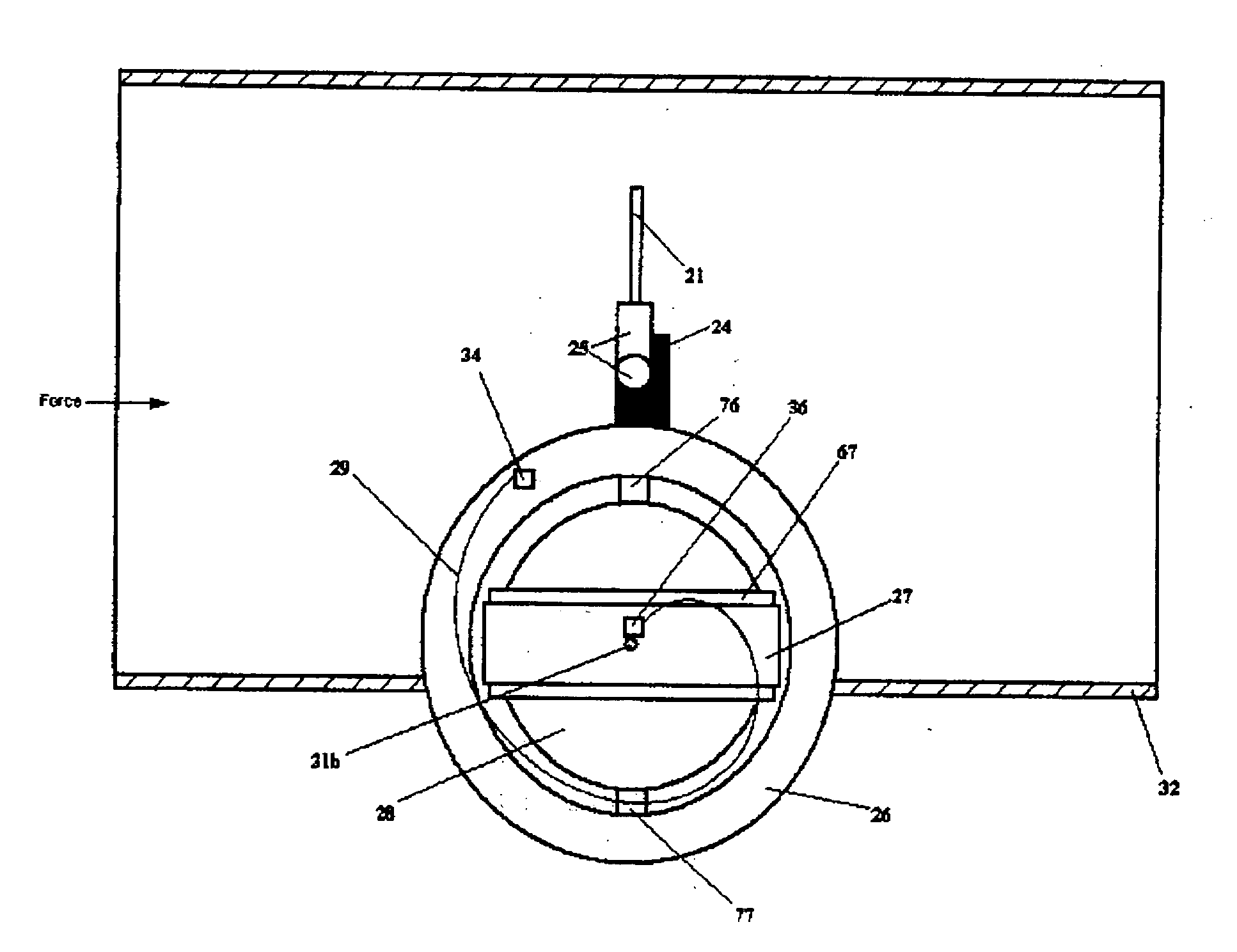
[0011]FIG. 3 and FIG. 4 show the second embodiment.

[0012]Element of means of sensing pressure is item 21. When pressure on the left of item 21 in FIG. 3 is greater than pressure on the right, item 21 generates a clockwise torque around axle 31. Elements of means of measuring position are light source 23, light sensor 25, and light path controller 24. (see FIG. 4) The further the item 21 has gone the path controller 24 blocks more photo diodes in light sensor 25. Elements of means of returning to original position are gossamers 29 and 129, which generate anticlockwise torque great enough to bring item 21 to original position without input current in coil 27. Elements of means of generating anti-torque are magnet 26, magnet 28, and coil 27. When the moving magnitude of item 21 is to be limited, a microprocessor sends input current through coil 27. Magnetic field between magnet 26 and magnet 28 act on input current and generate anticlockwise anti-torque around axles 31 and 131. The ele...


PUM


Abstract

The primary application of this force meter is measurement of fluid flow. A force on the force sensor push the force sensor away from the original position. The deviation of the force sensor is detected by a proximity sensor. An electronic unit takes the position signal from the proximity sensor as a feedback. The electronic unit generates electric current to an electromagnetic anti-torque means. The electromagnetic anti-torque means generates an anti-torque on force sensor to prevent the force sensor from moving away from the original position. A display unit measures the electric current and calculates velocity and rate of fluid before displays the results.”

Description

CROSS REFERENCE TO RELATED APPLICATION[0001]This application is a continuation-in-part of U.S. Pat. No. 7,611,472BACKGROUND OF THE INVENTION[0002]The traditional apnea monitor measures the electrical resistance across the chest to sense breathing. These apnea monitors have both positive and negative false alarms. The reason that it does not give alarm when a baby stops breathing is that noise is too weak to detect. The reason that alarm goes off when the baby is healthy is that the noise is too strong. Where the noise comes from? Resistance of the chest is influenced by the liquid flow inside the body and the airflow inside the lung.SUMMARY OF THE INVENTION[0003]The present invention directly measures breathing airflow instead of measuring the resistance of the chest. The objective of the present invention is to increase sensitivity of apnea monitor. Another objective is to measure vital capacity. The present invention collects parameters about breathing. Based on the parameters, vi...

Claims


Application Information

Patent Timeline
Patent Type & Authority Applications(United States)
IPC IPC(8): A61B5/09
CPCA61B5/0826A61B5/6803A61B5/09
Inventor LU, GUIXIAN
Owner LU GUIXIAN
Why Eureka
Try Eureka