

Exhaust heat exchanger
a heat exchanger and exhaust technology, applied in the direction of heat exchange apparatus safety devices, machines/engines, light and heating apparatus, etc., can solve the problems of easy lowering of mechanical connection strength between the flange and the egr gas pipe, inability to secure the strength of the inlet gas tank, and low heat resistivity of aluminum
- Summary
- Abstract
- Description
- Claims
- Application Information
AI Technical Summary
Benefits of technology
Problems solved by technology
Method used
Image

Examples
first embodiment
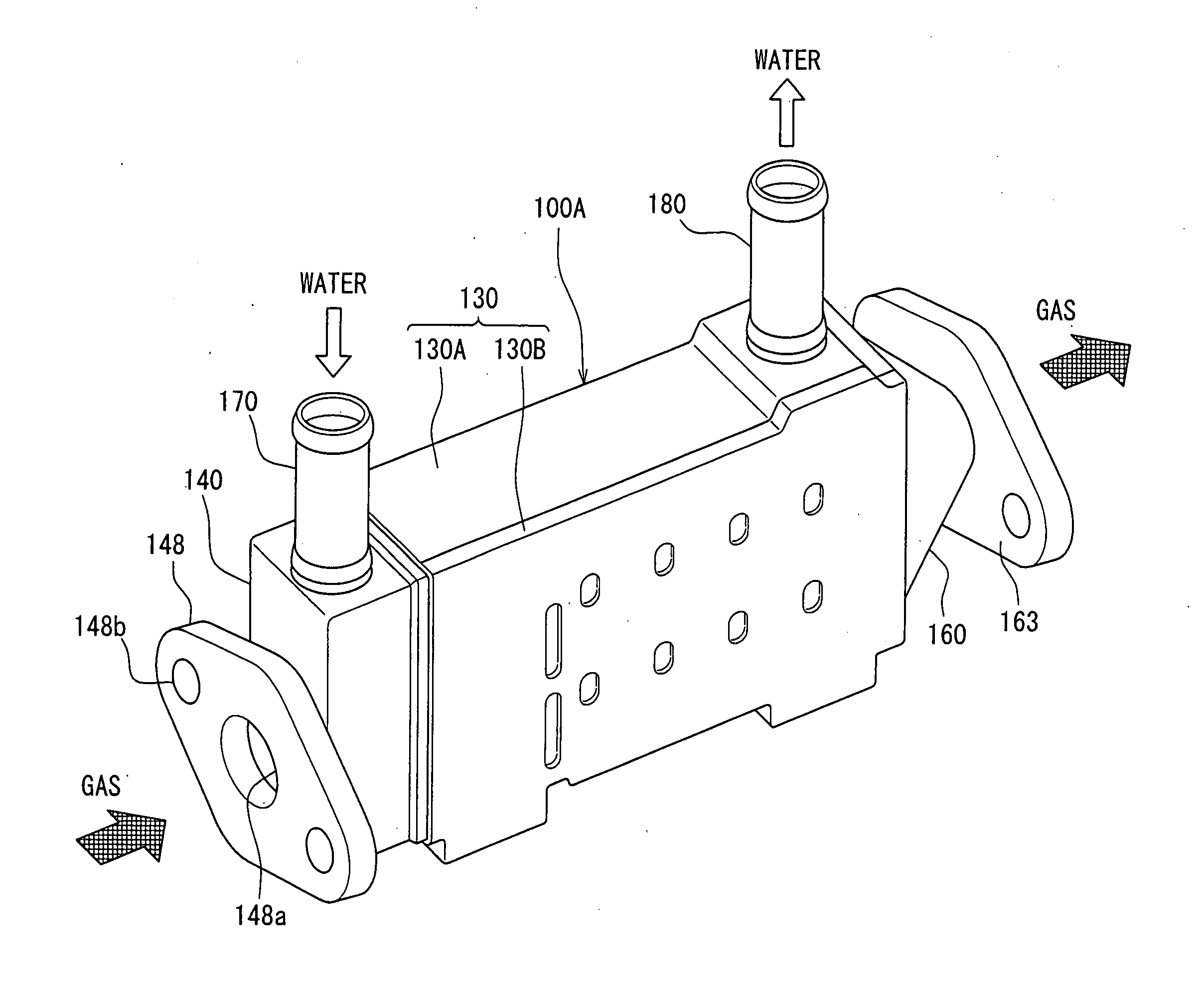
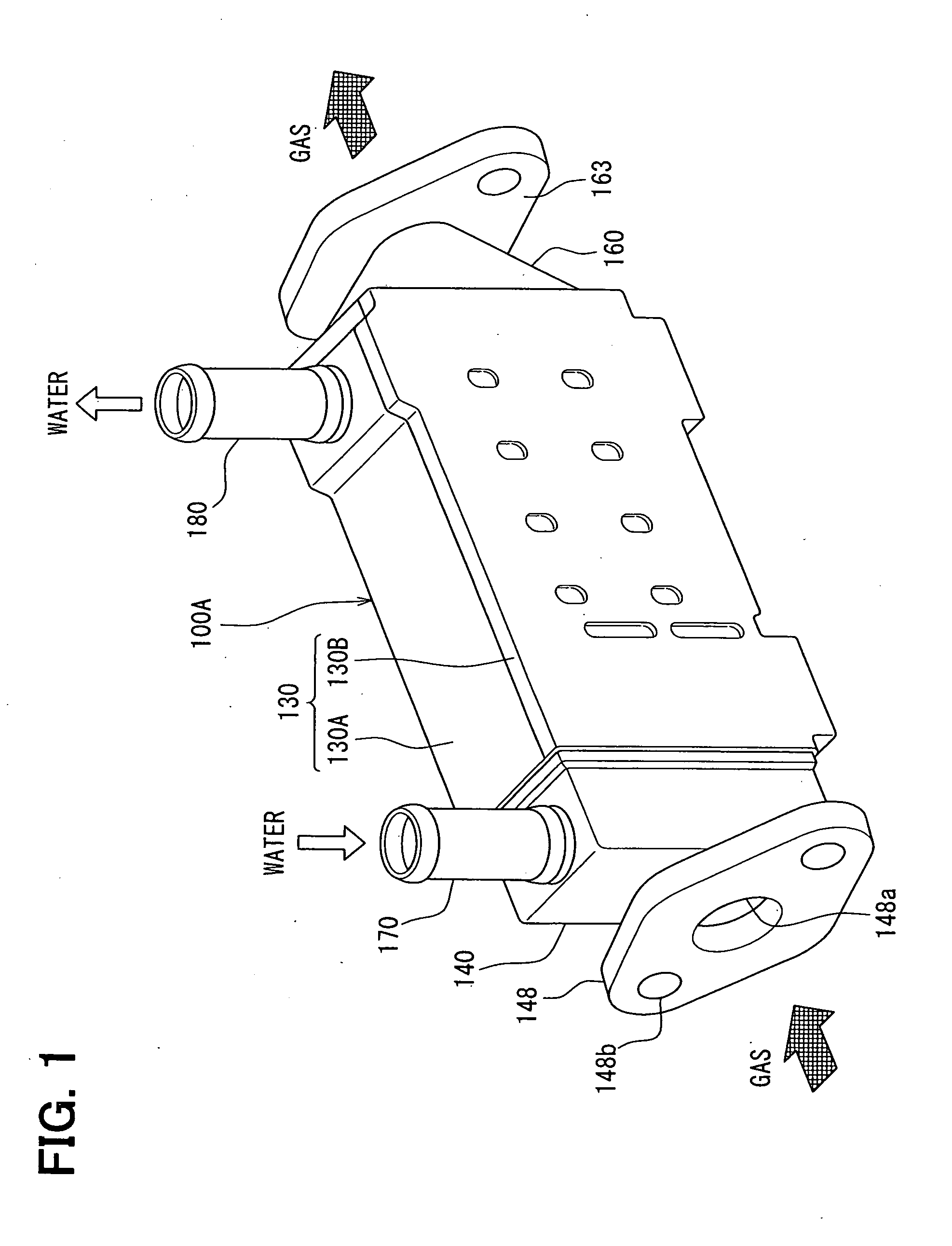
[0036]In a first embodiment, an exhaust heat exchanger is a gas cooler 100A used for an exhaust gas recirculation (EGR) apparatus of a diesel or gaoline engine, for example.
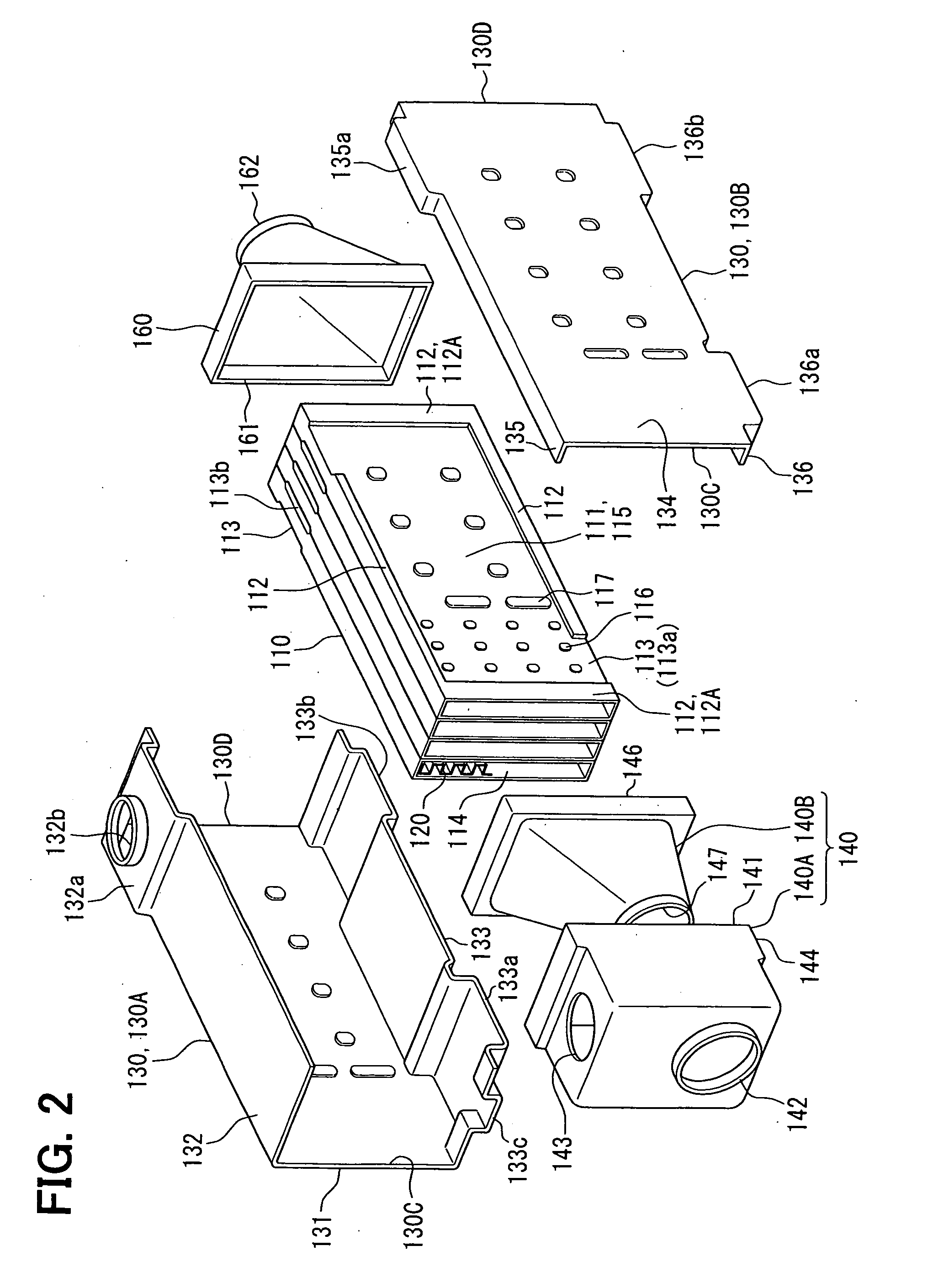
[0037]FIG. 1 is a perspective view illustrating the gas cooler 100A, and FIG. 2 is an exploded view of FIG. 1. FIG. 3 is a perspective view illustrating a lower side of the gas cooler 100A by reversing an upside of FIG. 1 down. FIG. 4 is a cross-sectional view of the gas cooler 100A. Definitions of up and down are used only for easy understanding, and are not limited in a real situation.
[0038]The gas cooler 100A cools exhaust gas to be recirculated into an intake side of the engine using water for cooling the engine. The cooling water may correspond to cooling fluid. As shown in FIG. 2, the gas cooler 100A includes tubes 110, inner fins 120 respectively arranged inside of the tubes 110, a water tank 130, an inlet gas tank 140, and an outlet gas tank 160. Further, as shown in FIG. 1, the gas cooler 100A includes a...
second embodiment
[0072]An EGR gas cooler 100B of a second embodiment will be described with reference to FIGS. 5 and 6. The outside tank 140A of the gas tank 140 and the water tank 130 of the first embodiment are integrally formed in the second embodiment. Further, flowing directions of cooling water and exhaust gas are changed, and the gas cooler 100B further includes a communication portion 151 other than the communication portion 150.
[0073]As shown in FIG. 5, the recess 113 of the tube 110 is defined at two positions on the same longer side of the base face 111. The inlet opening 113a and the outlet opening 113b are located on the same side face of the layered tubes 110. Therefore, the water passage 115 has a U-shape.
[0074]The water tank130 has a first part 130A arranged on an upper side of the tube 110, and a second part 130B arranged on a lower side of the tube 110. The first part 130A has an expansion 132c at a position corresponding to the inlet opening 113a, and an expansion 132a at a positi...
third embodiment
[0082]A gas cooler 100C of a third embodiment will be described with reference to FIGS. 7 and 8. Compared with the first embodiment, the inlet water pipe 170 is connected to the water tank 130, and the gas cooler 100C further includes a communication portion 151 other than the communication portion 150, in the third embodiment.
[0083]As shown in FIG. 7, the recess 113 of the tube 110 is defined at two positions on the same longer side of the base face 111. The inlet opening 113a and the outlet opening 113b are located on the same side face of the layered tubes 110. Therefore, the water passage 115 has a U-shape.
[0084]The water tank 130 has an expansion 132c at a position corresponding to the inlet opening 113a, and an expansion 132a at a position corresponding to the outlet opening 113b. As shown in FIG. 8, the water tank 130 has an expansion 136c and an expansion 133b communicating with the expansion 136c. The expansion 136c opposes to a side face of the tube 110 opposite from the o...
PUM
 Abstract
Description
Claims
Application Information