
Nipple/Areola Protective Cover

a protective cover and nipple technology, applied in the field of nipple/areola protective cover, can solve the problems of wicking moisture past the skin barrier, and reducing the use of valuable operating room for other surgeries. , to achieve the effect of convenient us

Inactive Publication Date: 2011-10-13
POLLACK LARRY H
View PDF10 Cites 44 Cited by
  • Summary
  • Abstract
  • Description
  • Claims
  • Application Information

AI Technical Summary

Benefits of technology

[0014]The device and method herein disclosed and described provides a novel solution to the above noted shortcomings in the prior art of bandaging delicate tissues transplanted and reformed during breast reconstruction surgery. In use, the device and method of employment provides an easily employed means to protect the nipple tissue and areola tissue as needed for post operation of breast and / or nipple reconstructive surgery.
[0015]Used in combination with substantially transparent tape or bandaging, the device consists of a body formed of a cylindrical resilient member with a top surface, bottom surface, side wall, and central aperture surrounded by the annular ring portion of the resilient member. The body of the device is formed of resilient or pliable material which compresses predictably when biased against the tissue of the patient by an adhesive bandage layer. The durometer of the body material is such that it will not cause abrasion to the skin or tissue if compressed or slid.
[0018]Thereafter, a clear or transparent tape or bandage material is positioned to cover the body and adhesively engage the patient's skin surrounding the areola which is covered by the bottom surface of the body. A slight but uniform pressure is exerted to slightly compress the material forming the body in the direction of its center axis. This compression and resulting outward biasing of the material forming the cylindrical body provide a means to exert a controlled bias of the underlying skin forming the areola, against underlying tissue, to encourage re-attachment but concurrently prevent cessation of blood flow.
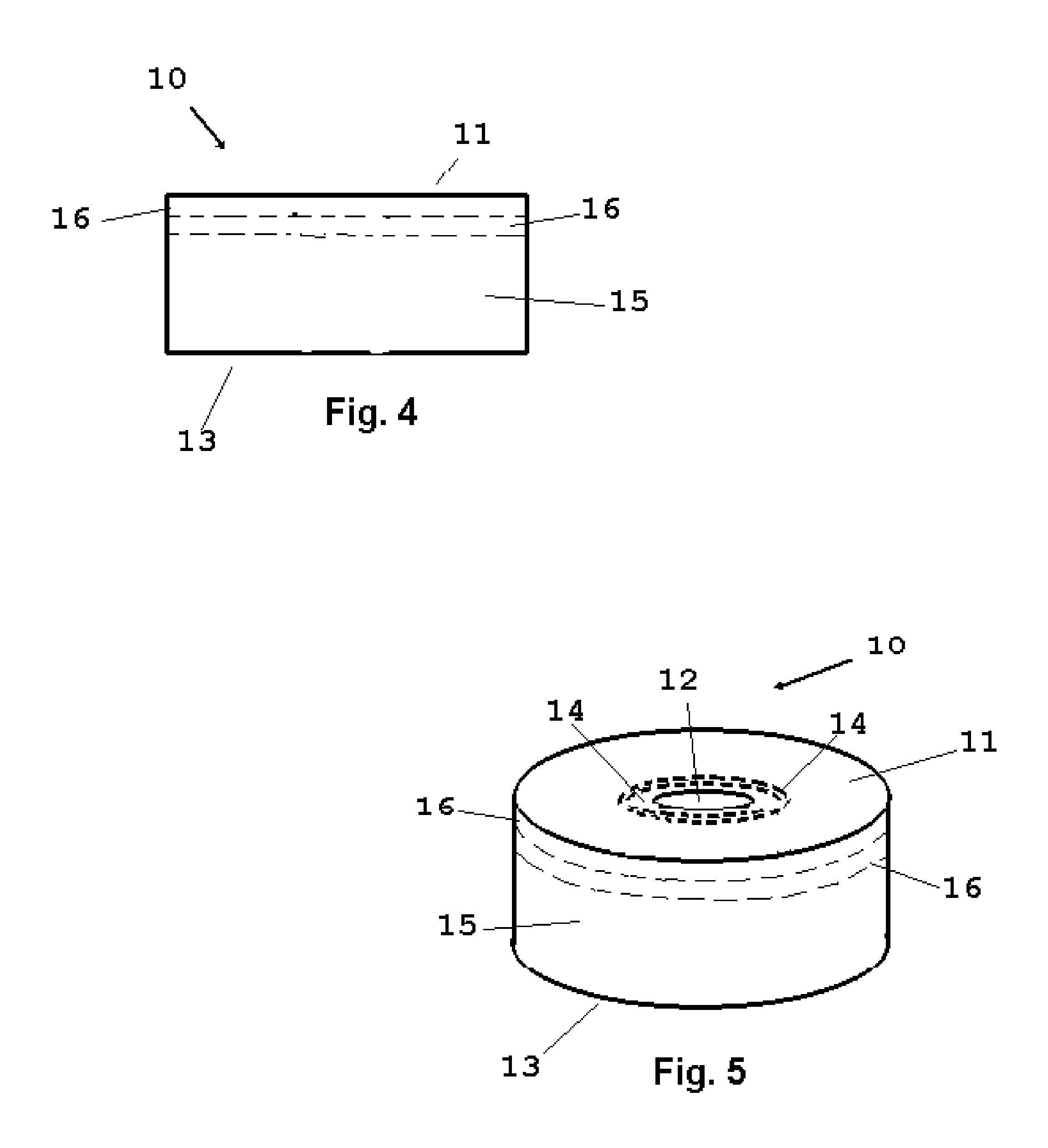
[0020]In an alternative mode, allowing sizing by the surgeon, the cylindrical body may be provided with a plurality of frangible sections which may be removed to alter one or both of the axial cavity diameter and the circumference. The foam or soft material forming the body would be formed in somewhat of a cinnamon roll type configuration where the material forming the body is sliced in coaxial rings allowing removal of circular portions to change the diameter of the axial cavity and the exterior circumference. This mode of the device lessens the number of different sized cylindrical bodies that may have to be provided the surgeon, lessening the amount of surgical room inventory. If desired, one or a plurality of horizontal cuts may be formed to allow a variation of the height of the formed body.
[0028]Still another object of the invention is to allow for a means of early detection of bleeding or infection occurring at the operation site such as soaking the device in reacting agents.

Problems solved by technology

This procedure is at times lengthy and requires much practice and tends to make the cessation of a surgery unpredictable causing decreased use of valuable operating rooms for other surgeries.
Additionally, there are many problems with this method.
Given the rigidity of the cap portion of the syringe employed, there is a potential for it to sever off or over compress the tissue forming the nipple it protects.
Additionally, since the gauze material used for support and padding is sewn to the skin, the resulting bandage is not water proof and can wick moisture past the skin barrier and showering must be avoided or extra care must be taken when showering.
In another problem with such bandaging, should the surgical site subsequently bleed or become infected, because the gauze is thick and has a bottom layer that is absorbent of fluids, the infection will not be noticeable to the patient.
This lack of patient viewing capability can cause a significant increase in the travel and severity of the infection until the fluids draining from it have soaked through the padding to alert the patient.
However, Hammer fails to take into account that patients have varying nipple sizes and lacks adjustment for such.
Further, the material of the device in Hammer is taught to be of high durometer rendering the device very hard which, if compressed by bandaging or impact, can damage the operation site.
The Hammer device also lacks any means to determine the force or amount of pressure which is being applied to the nipple and areola tissue by the bandaging.
Since excess pressure can cut off blood flow or damage tissues, Hammer lacks any provision to protect this important aspect of the healing process.

Method used


Image

  • Nipple/Areola Protective Cover
  • Nipple/Areola Protective Cover
  • Nipple/Areola Protective Cover

Examples


Embodiment Construction

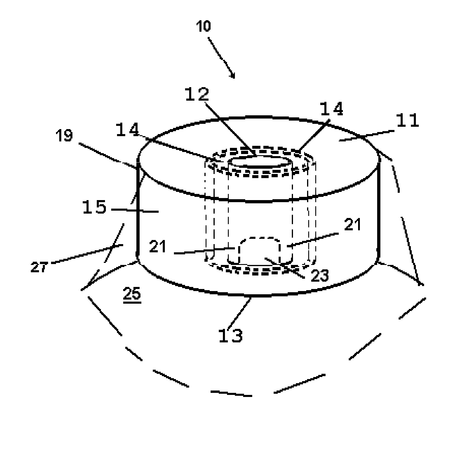
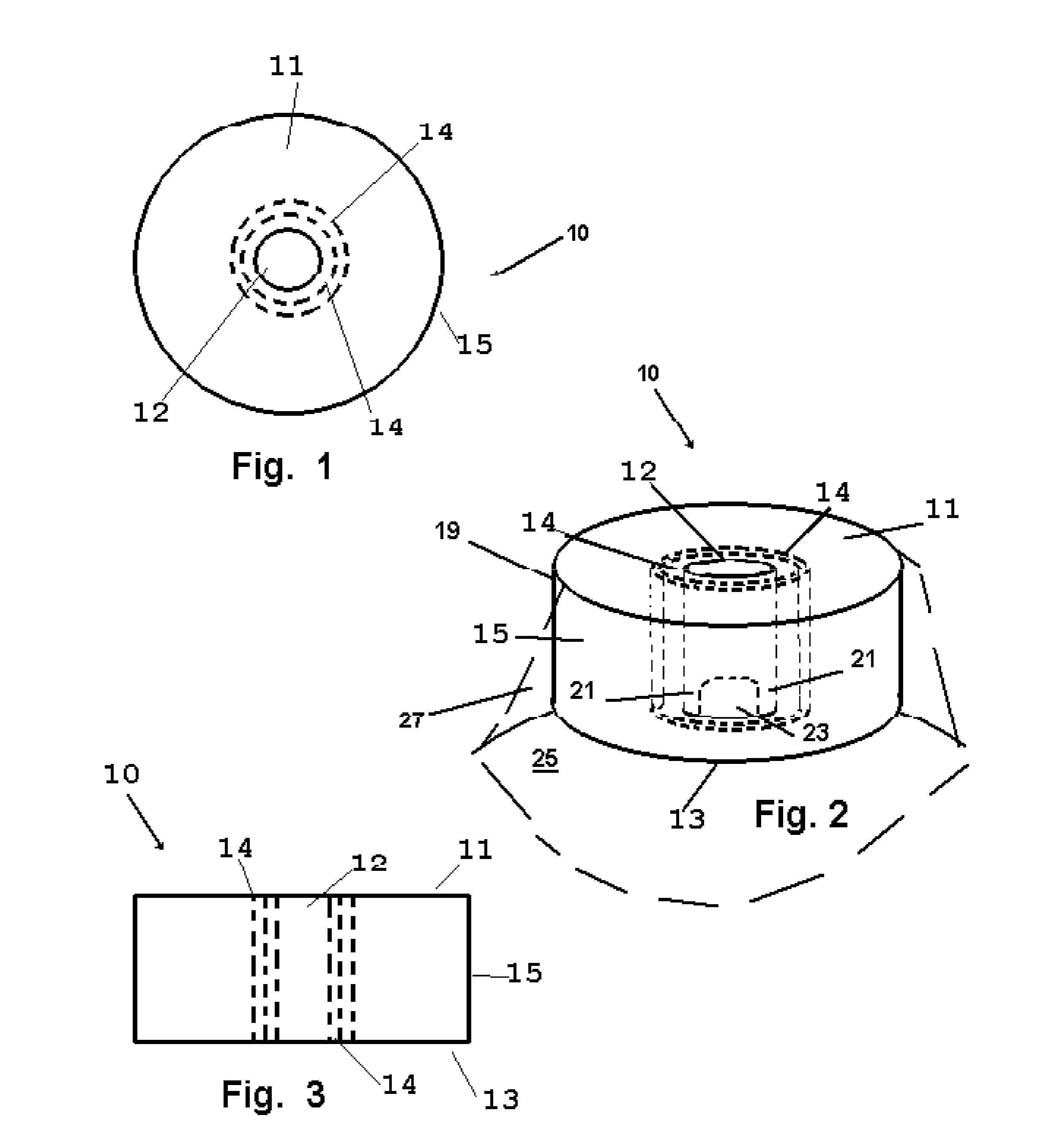
[0039]Now referring to drawings in FIGS. 1-8, wherein similar components are identified by like reference numerals, there is seen in FIG. 1 the device 10 depicting the axial cavity 12, defined by an annular sidewall surrounding the center axis of the axial cavity 12. Also shown are a first or top surface 11 and a sidewall 15 which defines the outer circumference and overall diameter of the device 10.

[0040]In the mode of the device 10 shown in FIGS. 1-3, a means to adjust the diameter of the axial cavity 12 is provided by one or a plurality of frangible portions of a central portion of the resilient member or body 19 which are removably engaged concentric cylindrical members 14. The material forming the body 19 being resilient, such as foam, it may be perforated or slit partially between the top and bottom surfaces to allow for the easy removal of the central portion formed by cylindrical members 14 removably attached to the body 19 in series, to enlarge the diameter of the axial cav...


PUM


Abstract

A protective cover for nipples and areolas employable during nipple or breast reconstructive surgery. The device has an axial cavity in a central portion of a resilient body employable for placement about the nipple or reconstructed nipple therein. The device is infinitely customizable in axial cavity diameter and vertical height by means of one or a plurality of removably engaged central portions.

Description

BACKGROUND OF THE INVENTION[0001]1. Field of the Invention[0002]This invention relates to medical devices employed for patient bandaging. More particularly, the disclosed device and method relate to medical devices employed during nipple reconstructive surgery and related surgeries. The disclosed device and method herein, provide a particular improvement in the art of bandaging a surgical patient to provide a means to protect the nipple and areola of a breast subsequent to reconstructive surgery.[0003]2. Prior Art[0004]Breast reconstructive surgeries have become commonplace in today's medical world whether the surgery is employed for medical reasons or for cosmetic purposes. Conventionally, breast reconstructive surgery and nipple related surgeries done concurrently or as a separate procedure, will involve a partial to full removal of the nipple and areola from the patient's breast.[0005]In some surgeries, a nipple must be constructed by the surgeon who, using surgical skill, employ...

Claims


Application Information

Patent Timeline
Patent Type & Authority Applications(United States)
IPC IPC(8): A61J13/00
CPCA61F15/008A61F2013/00165A61F2013/00272A61F2013/00382A61F13/145A61F2013/00825A61F2013/00846A61J13/00A61F13/141A61F2013/00634
Inventor POLLACK, LARRY H.
Owner POLLACK LARRY H
Learn More