Heat exchanger maintenance technique

a technology of heat exchangers and maintenance techniques, applied in indirect heat exchangers, flush cleaning, lighting and heating apparatus, etc., can solve the problems of significant impairing the performance of heat exchangers, reducing the capacity of heat exchangers, and reducing the service life of heat exchangers. achieve the effect of high capacity

Active Publication Date: 2011-10-13
DIXON CHRISTOPHER J +2
View PDF26 Cites 24 Cited by
  • Summary
  • Abstract
  • Description
  • Claims
  • Application Information

AI Technical Summary

Benefits of technology

[0012]It is an object of this invention to provide an improved method and apparatus for cleaning, testing, inspecting and / or plugging heat exchanger tubes while the heat exchanger is in operation.
[0013]A more specific object of this invention is to provide an improved method and apparatus for cleaning heat exchanger tubes while the heat exchanger is in operation utilizing brushes which may be incorporated into the heat exchanger.
[0014]A further object of this invention is to provide a heat exchanger having a compartment wall designed to accommodate the leak free insertion of tube isolation tools and or other maintenance equipment during operation of the heat exchanger at high capacity.
[0015]These and other objects and advantages of this invention will become more apparent as this description proceeds, reference being made to the accompanying drawings and appended claims.

Problems solved by technology

Straight through heat exchangers are typically selected when the tube side fluid deposits materials in the tube or is corrosive because it is usually more difficult to clean the curve in a U-tube type.
The performance of shell and tube heat exchangers degrades over time by the deposition of solids from the tube side flow onto the inside wall of the heat exchanger tubes.
This is commonly referred to as tube side fouling and can significantly impair the performance of heat exchangers.
This fouling can also cause increased pressure drops across the tubes thereby decreasing flow through the tubes.
Under certain conditions, these deposits can also promote corrosion of the inside of the tube wall, a phenomenon known as under-deposit corrosion.
This corrosion, if left unchecked, can produce leak paths through the tube wall allowing commingling of the heat exchange fluid and the process fluid.
These deposits are often relatively hard and therefore difficult to remove from the tube walls.
The cost of disassembling and then reassembling the heat exchanger to permit access to the tubes for cleaning and inspection can be significant.
More significant in many situations is the lost production cost from taking the heat exchanger and its associated equipment out of service.
The costs associated with reduced capacity of heat exchanger tubes can also be substantial in situations where the throughput of process fluids has to be curtailed.

Method used


Image

  • Heat exchanger maintenance technique
  • Heat exchanger maintenance technique
  • Heat exchanger maintenance technique

Examples


Embodiment Construction

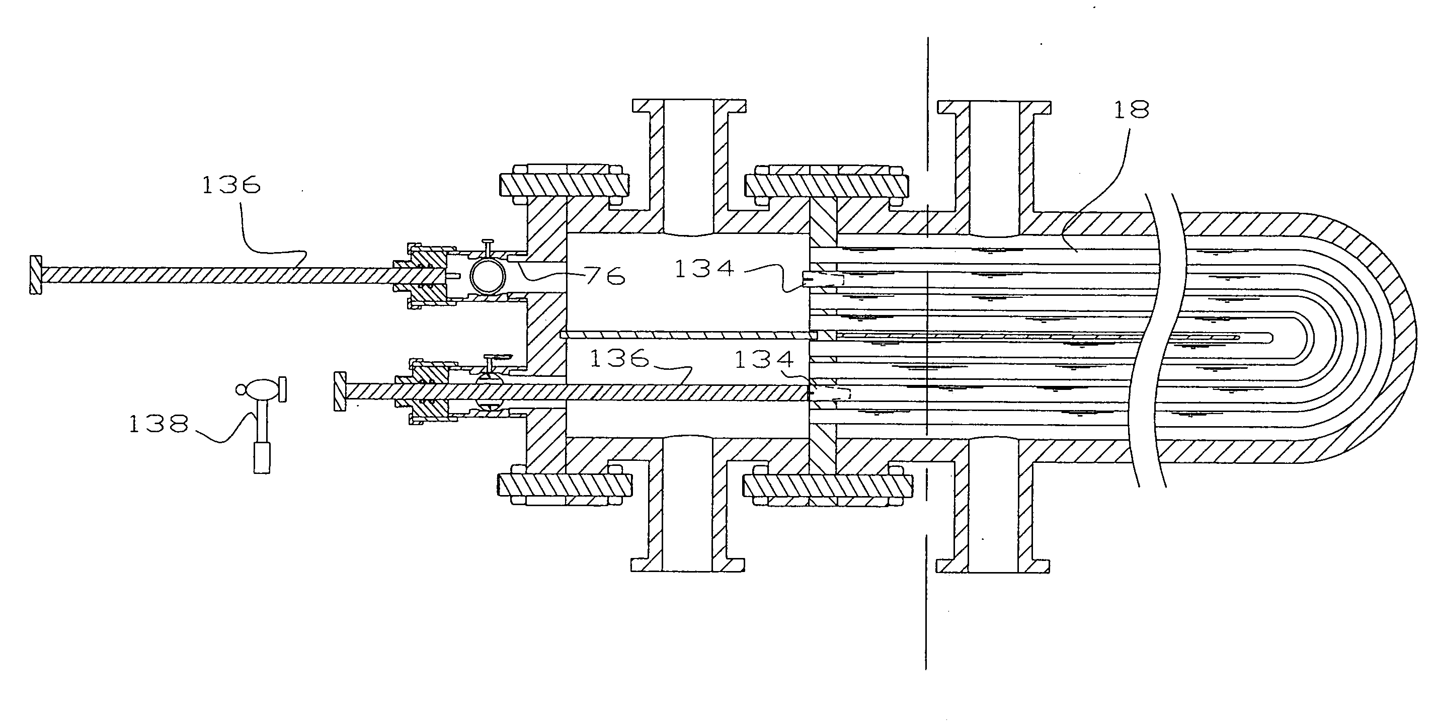
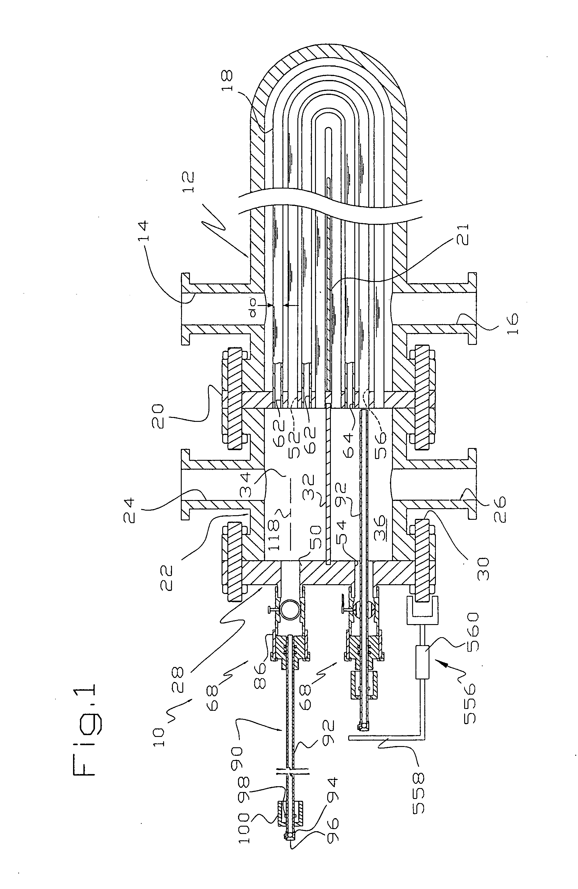
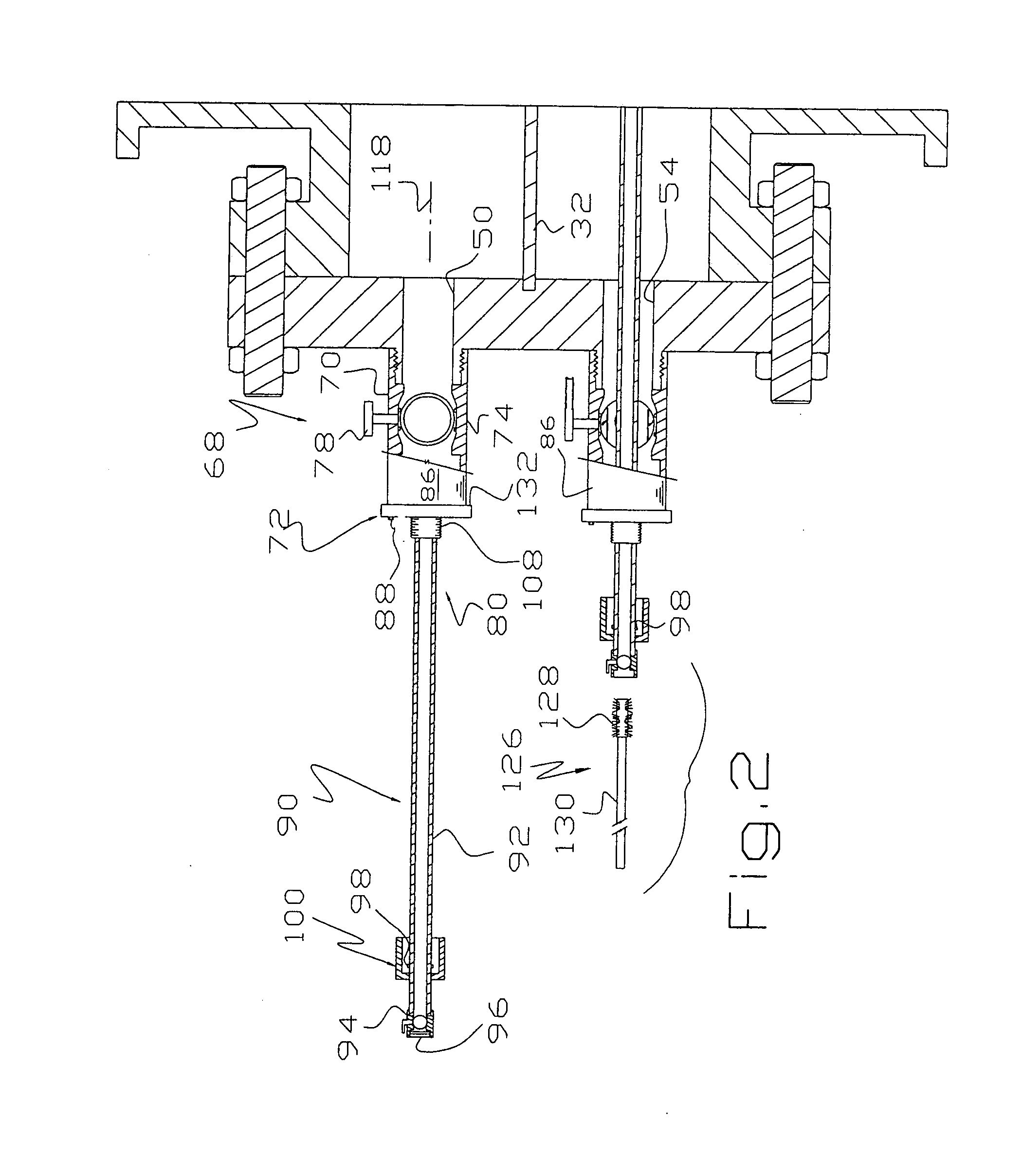
[0040]Although there are a variety of embodiments disclosed which involve cleaning, inspecting, testing and / or plugging of heat exchanger tubes while the exchanger is in operation, it is understood that these embodiments are merely suggestive of numerous other approaches or techniques which may be adopted for these purposes. In general, descriptive statements do not delimit the claims in this application and some statements relative to one embodiment or feature are not necessarily applicable to other embodiments or features.

[0041]Tubular heat exchangers come in many forms and have many names. Some of the more common industrial heat exchangers that can be cleaned, inspected, tested and / or plugged with the devices disclosed herein include shell and tube heat exchangers, boilers, surface condensers and air cooled fin tube exchangers. In one sense, the disclosed devices operate on the inside of the tubes and what occurs on the outside of the tubes may be of any description. The devices ...


PUM

PropertyMeasurementUnit
pressureaaaaaaaaaa
pressureaaaaaaaaaa
wall thicknessaaaaaaaaaa

Abstract

A heat exchanger is cleaned, inspected and/or plugged while the heat exchange is in operation. In some embodiments, the heat exchanger comprises a channel cover having valve-seal assemblies allowing isolation tools to be inserted through the channel cover into sealing engagement with the ends of tubes to provide a flow path separate from the normal flow paths through the heat exchanger. Cleaning and/or inspecting can be done through the isolation tools and tubes that are leaking can be plugged through the valve-seal assemblies. In some embodiments, brushes are located inside the heat exchanger and can be independently advanced into cleaning relation with a large majority of the tubes.

Description

[0001]This application is based on Provisional Applications Ser. No. 61 / 322,851, filed Apr. 10, 2010 and Ser. No. 61 / 351,877 filed Jun. 5, 2010, priority of which is hereby claimed, the disclosures of which are incorporated herein by reference.[0002]This invention relates to a method and apparatus for inspecting, testing, cleaning and / or plugging tubes of a heat exchanger while the heat exchanger is in operation.BACKGROUND OF THE INVENTION[0003]There are several types of heat exchangers used in various industries. A common type is known as a shell and tube type. Modern shell and tube exchangers are of several types, including: (1) a straight through version where the heat exchange tubes are generally straight, (2) a U-tube version where the heat exchange tubes are bent into a U so the inlets and outlets of the heat exchange tubes pass through the same tube sheet and open into compartments provided by a channel and (3) a floating head type where the inlets and outlets are at one end ...

Claims


Application Information

Patent Timeline
Patent Type & Authority Applications(United States)
IPC IPC(8): F28F27/00F28F1/00F28F9/02B21D53/02
CPCF28D7/16F28F9/007F28F11/02Y10T29/4935F28G3/04F28G9/00F28G15/08F28G1/02
Inventor DIXON, CHRISTOPHER J.REEVES, RONALD G.PARKER, RYAN E.
Owner DIXON CHRISTOPHER J
Why Eureka
Try Eureka