Method and device for the friction stir welding of two components

a technology of friction stir and two components, which is applied in the direction of welding devices, soldering devices, manufacturing tools, etc., can solve the problems of causing ‘penetration defects’ or ‘lop’ (lack of penetration) defects, and thus high production cost of rivet connections of this typ

Active Publication Date: 2011-10-13
AIRBUS OPERATIONS GMBH
View PDF6 Cites 22 Cited by
  • Summary
  • Abstract
  • Description
  • Claims
  • Application Information

AI Technical Summary

Benefits of technology

[0007]The object of the present invention is therefore to provide an improved method for connecting two components, which method does not have the aforementioned drawbacks.

Problems solved by technology

Rivet connections of this type are thus expensive to produce and signify an undesired increase in weight in the seam region.
If the depth of the remaining region exceeds a tolerance limit, ‘penetration defects’ or ‘LOP’ (lack of penetration) defects may be produced owing to internal tensile stresses induced in the material and insufficient material plasticisation.
Such LOP defects significantly reduce the fatigue limit of welds produced by friction stir welding.
However, when welding large components with long welds, for example as is the case when constructing fuselage and aerofoil sections, compliance with such narrow tolerances is hugely complex from a technical point of view and is therefore virtually impossible.
Furthermore, when using this tool the weld is visible from each side, which is not desirable for example when connecting two components which form a visible surface.
Furthermore, the use of the bobbin friction stir welding tool means that the time and therefore cost involved is higher compared to the friction stir welding pin tool.
This finishing, by machining, of the connection region also involves considerable additional time.

Method used


Image

  • Method and device for the friction stir welding of two components
  • Method and device for the friction stir welding of two components
  • Method and device for the friction stir welding of two components

Examples


Embodiment Construction

[0036]In the figures, like reference numerals refer to like or functionally similar components unless information to the contrary is given.

[0037]A preferred embodiment of the present invention will be described hereinafter with reference to FIGS. 1 to 7.

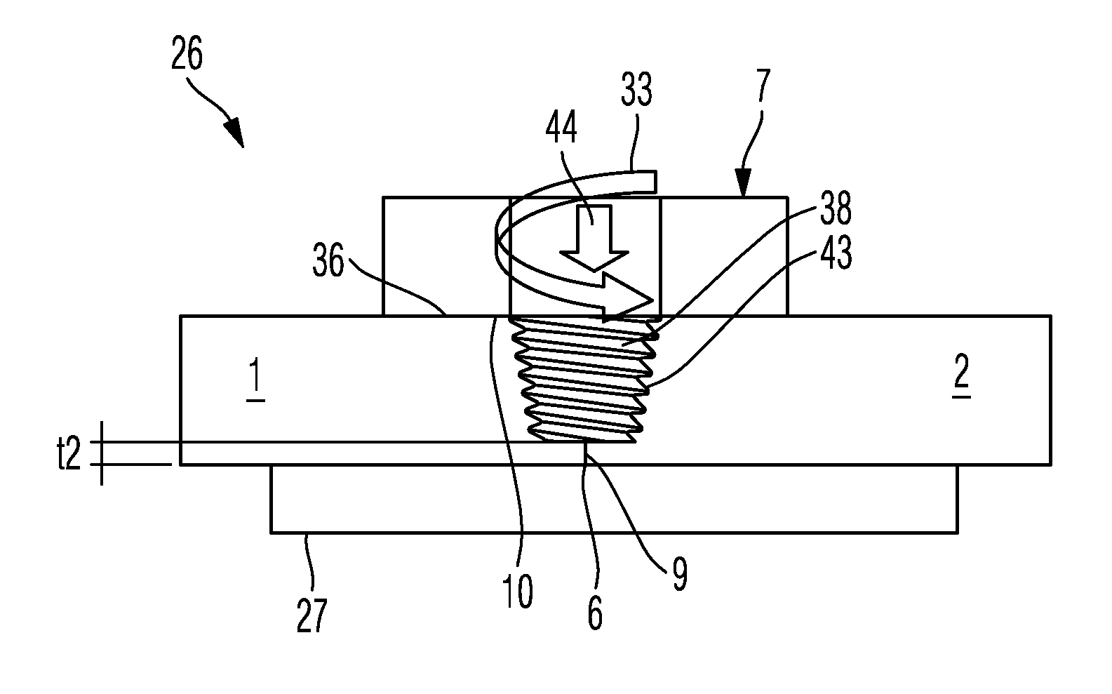
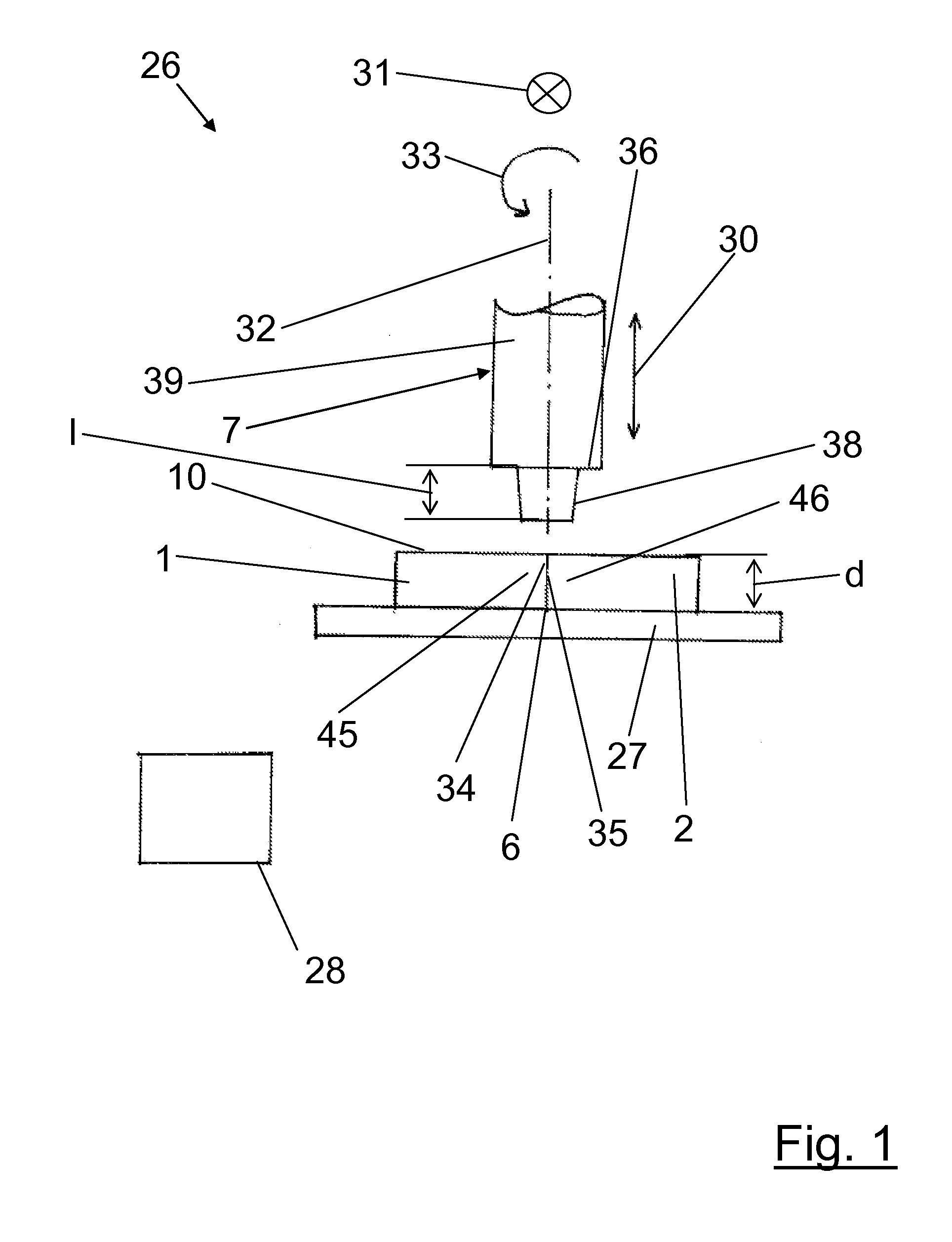
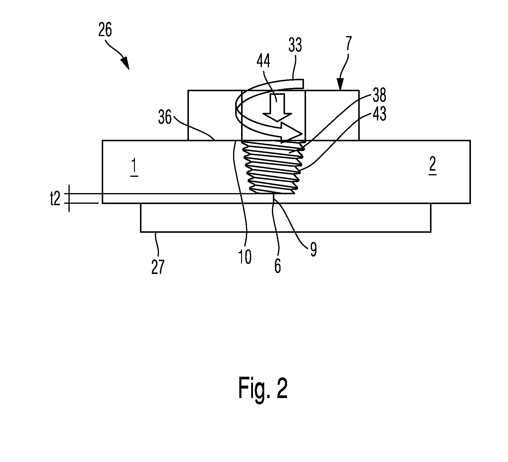
[0038]FIG. 1 shows a device 26 for the friction stir welding of two components 1, 2. The device 26 comprises a positioning means 27, which is preferably formed as a support rest 27 in the form of a plate-shaped rest, and a friction stir welding tool 7. The positioning means 27 is an optional component of the device 26. The friction stir welding tool 7 can be moved towards the positioning means 27 in the vertical direction. This possibility for movement is illustrated by the arrow 30. As illustrated by the arrow 31, the friction stir welding tool 7 is movable along a connection region 6 formed between the two components 1, 2. The friction stir welding tool 7 is substantially cylindrical. For example, it comprises a cylinder 39 with a ...


PUM

PropertyMeasurementUnit
depthaaaaaaaaaa
thickness t2aaaaaaaaaa
internal compressive stressesaaaaaaaaaa

Abstract

A method for the friction stir welding of two components, in particular of two shell components of a fuselage structure of an aircraft and spacecraft, said method comprising the following method steps: positioning the two components relative to one another in such a way that a connection region is formed between the two components; friction stir welding the two components by means of a friction stir welding tool which penetrates the connection region in order to produce a weld which permeates the connection region with the formation of an unpenetrated weld edge portion of the connection region; and introducing internal compressive stresses, at least in the weld edge portion of the connection region. Further a device for the friction stir welding of two components, in particular of two shell components of a fuselage structure of an aircraft and spacecraft is provided.

Description

CROSS-REFERENCE TO RELATED APPLICATIONS[0001]This application claims the benefit of and priority to U.S. Provisional Application No. 61 / 321,990, filed Apr. 8, 2010 and German Patent Application No. 10 2010 003 742.7, filed Apr. 8, 2010, the entire disclosures of which are herein incorporated by reference.FIELD OF THE INVENTION[0002]The present invention relates to a method and a device for the friction stir is welding of two components, in particular of two shell components of a fuselage structure of an aircraft and spacecraft.[0003]In passenger aircraft and transport aircraft construction aluminium fuselage shell segments are generally riveted together along longitudinal seams. This requires, in addition to an overlap between the components to be connected in the seam region, a large number of individual components that have to be used. Rivet connections of this type are thus expensive to produce and signify an undesired increase in weight in the seam region.[0004]An alternative jo...

Claims


Application Information

Patent Timeline
Patent Type & Authority Applications(United States)
IPC IPC(8): B23K20/12
CPCB23K20/123B23K31/02B23K20/122B23K20/124B23K37/08B23K20/126B23K20/002B23K20/1245B23K20/1275B23K20/129B23K20/26
Inventor FURFARI, DOMENICOPACCHIONE, MARCO
Owner AIRBUS OPERATIONS GMBH
Why Eureka
Try Eureka