Light emitting device

a technology of light emitting device and light source, which is applied in the direction of semiconductor devices, basic electric elements, electrical apparatus, etc., can solve the problems of color unevenness and other problems, and achieve the effects of high light extraction efficiency, reduced color unevenness, and reduced color unevenness

Active Publication Date: 2011-10-13
NICHIA CORP
View PDF4 Cites 21 Cited by
  • Summary
  • Abstract
  • Description
  • Claims
  • Application Information

AI Technical Summary

Benefits of technology

[0011]According to the present invention, the first wavelength converting member, the light emitting element, and the second wavelength converting member are stacked in this order on the bottom surface of the housing member through the light transmissive supporting member. Therefore, light can be extracted efficiently from the underside of the light emitting element. Further, placing the first wavelength converting member made of an inorganic binder and a fluorescent material beneath the light emitting element and placing the second wavelength converting member over the first wavelength converting member suppress the occurrence of the color unevenness while maintaining high light extracting efficiency. That is, the first wavelength converting member located beneath the light emitting element may be a plate shape member which is a composite of an inorganic binder and a fluorescent material, but the difference in the refractive index between the inorganic binder and the fluorescent material is relatively small and therefore, the light passing through the first wavelength converting member is not much scattered. Therefore, contrary to the case using a fluorescent material layer 82 made of a resin and fluorescent material particles shown in FIGS. 9(a) and 9(b), the amount of returning light to the light emitting element due to the scattering in the first wavelength converting member is small. On the other hand, in the plate shape first wavelength converting member, light tends to propagate in the lateral direction which results in strong emission at the end surfaces of the first wavelength converting member, thus, color unevenness tends to occur. Therefore, occurrence of color unevenness by the first wavelength converting member can be suppressed by forming a light scattering surface on at least a portion of the side surface of the recess portion to where the light emitted from a side surface of the first wavelength converting member in a direction parallel to the principal surface of the first wavelength converting member is incident. The first wavelength converting member and the light emitting element are spaced apart from the side surface of the recess portion where the scattering surface is formed, so that the amount of light returning to the light emitting element due to the scattering surface is relatively small.

Problems solved by technology

On the other hand, in the plate shape first wavelength converting member, light tends to propagate in the lateral direction which results in strong emission at the end surfaces of the first wavelength converting member, thus, color unevenness tends to occur.

Method used


Image

  • Light emitting device
  • Light emitting device
  • Light emitting device

Examples


Embodiment Construction

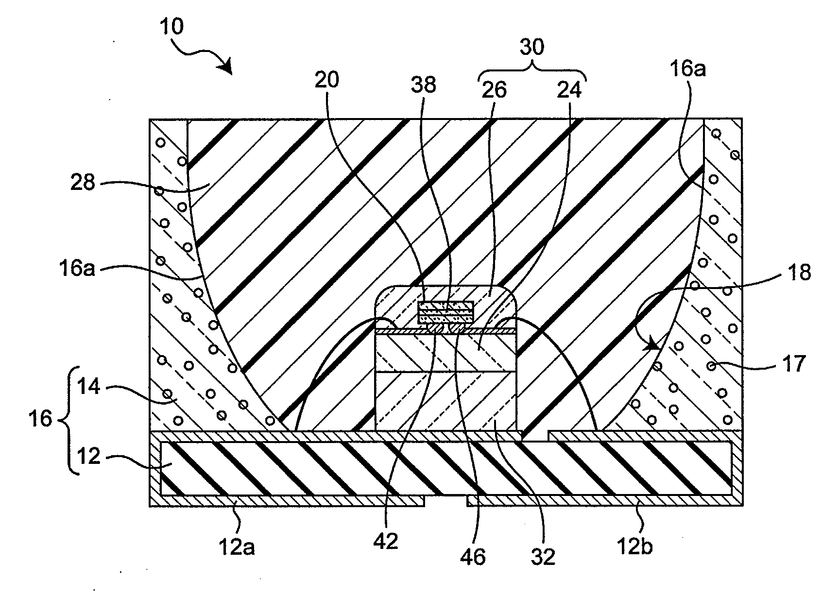
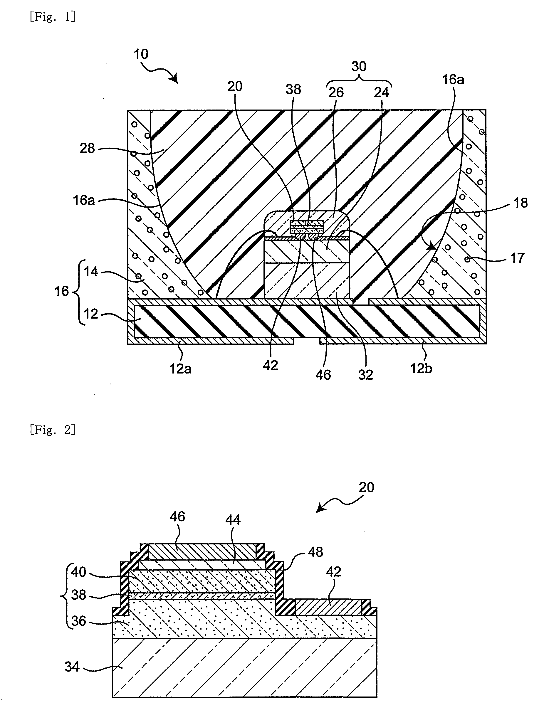
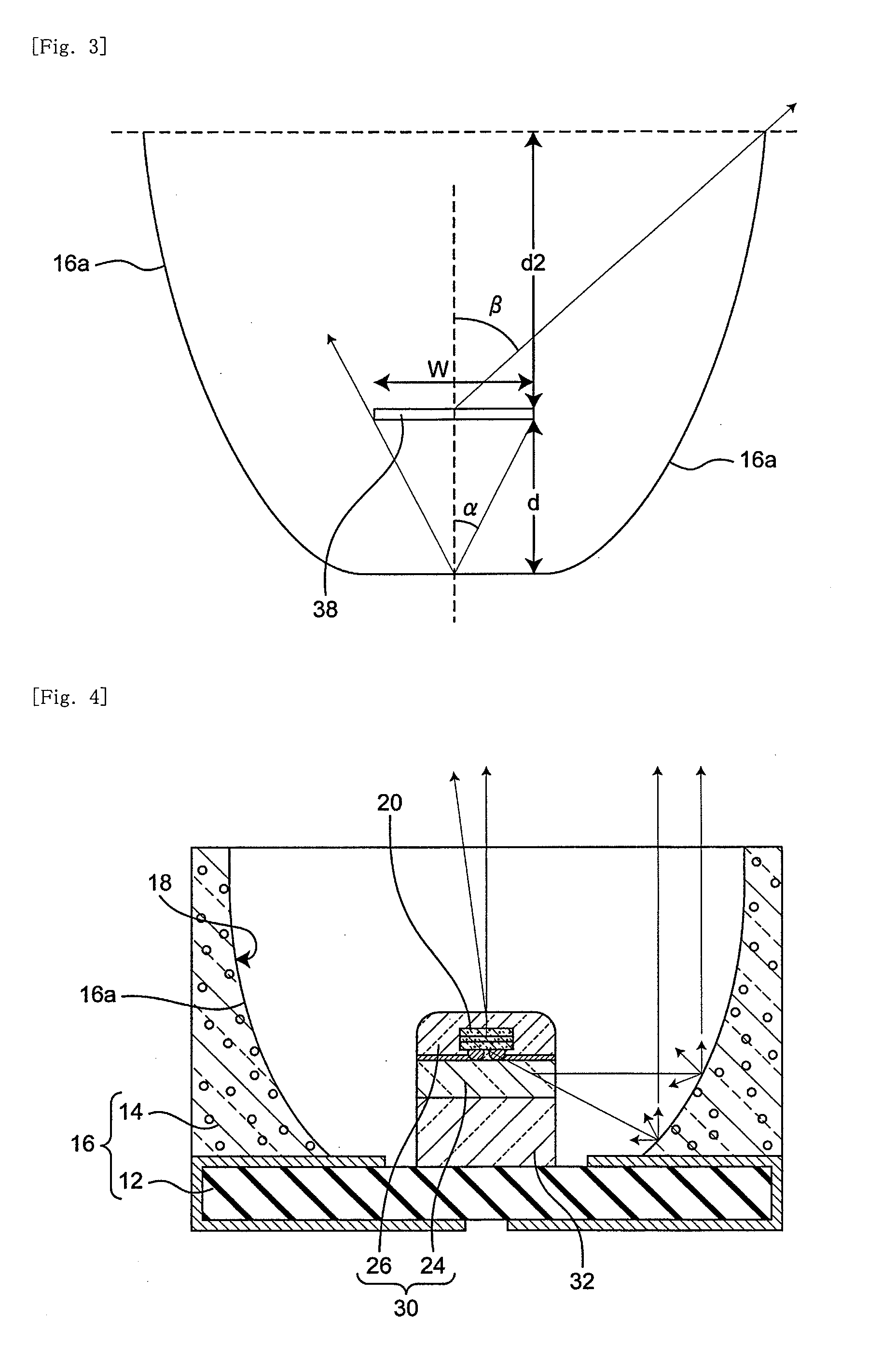
[0021]Preferred embodiments of the present invention will be described below with reference to the accompanying drawings. The drawings show the objects schematically, and information included therein such as layout, dimensions, proportion and shape may be different from the actual. The members using the same reference numeral as that of another embodiment in the respective embodiments denote the same or corresponding members, and description thereof may be omitted.

[0022]In the present specification, the terms “up” and “down” are used also to indicate the side of the light emitting device where emitted light is extracted and the opposite side, respectively. For example, the term “upward” indicates the direction of the light emitting device where emitted light is extracted, and the term “downward” indicates the opposite direction. Also, the term “top surface” indicates the surface one the side of the light emitting device where light is extracted, and “bottom surface” indicates the su...


PUM


Abstract

The first wavelength converting member, the light emitting element, and the second wavelength converting member are disposed in this order toward the opening of the recess portion on the bottom surface of the housing member through a light transmissive supporting member, and spaced away from the side surface of the recess portion. The first wavelength converting member is a plate shape member made of a composite of an inorganic binder made of an inorganic material and a fluorescent material. A light scattering surface is formed on at least a portion of the side surface of the recess portion, which is irradiated with the light emitted from the side surfaces of the wavelength converting member in parallel with the principal surface of the first wavelength converting member.

Description

[0001]This application claims priority from Japanese Patent Application No. 2010-88330, filed Apr. 7, 2010, the content of which is incorporated herein by reference, in its entirety.BACKGROUND OF THE INVENTION[0002]1. Field of the Invention[0003]The present invention relates to a light emitting device capable of effecting color-mixing of light emitted from a light emitting element and light obtained through wavelength conversion of a part of the original light, thereby emitting light of a different color.[0004]2. Description of Related Art[0005]A semiconductor light emitting element such as light emitting diode is small in size, has high power efficiency and emits light with clear color. The semiconductor light emitting element also has such advantages as almost free from blowout, excellent startup performance, and high durability to vibration and repetitive operations of turning on and off. There have been developed a light emitting device capable of emitting light of various wavel...

Claims


Application Information

Patent Timeline
Patent Type & Authority Applications(United States)
IPC IPC(8): H01L33/50H01L33/58
CPCH01L24/32H01L2224/32257H01L33/507H01L33/60H01L2933/0091H01L2224/48091H01L2224/73265H01L33/505H01L2224/32245H01L2924/3025H01L2224/48247H01L2924/01322H01L2924/12041H01L2224/92247H01L2224/8592H01L2224/48257H01L2924/00014H01L2924/00H01L2924/181H01L2924/00012
Inventor ICHIKAWA, MASATSUGU
Owner NICHIA CORP
Why Eureka
Try Eureka