
Organic el module and illumination device including same

Inactive Publication Date: 2011-10-13
PANASONIC CORP
View PDF1 Cites 10 Cited by
  • Summary
  • Abstract
  • Description
  • Claims
  • Application Information

AI Technical Summary

Benefits of technology

[0008]In view of the above, the present invention provides an organic EL module capable of reducing damages to electrode wirings provided at an organic EL panel during operation such as an operator's handling of the organic EL panel or the like and also capable of reducing contamination of the organic EL panel. In addition, the present invention provides an illumination device having a plurality of organic EL modules.
[0014]With the organic EL module described above, the extended portions protruding by a predetermined width are at least partially formed at the side surfaces of the casing where the electrode terminals of the organic EL panel are not disposed, and the extended portions can serve as handle portions for an operator. Accordingly, it becomes easier for the operator to hold the extended portions when handling the organic EL module of the present invention. Hence, the wirings can be prevented from damages which would be caused when the operator holds the vicinity of the electrode terminals, and the organic EL panel can be protected from contamination by fingerprints or the like. Further, the extended portions can facilitate positioning of a plurality of organic EL modules when the organic EL modules are arranged in the illumination device.

Problems solved by technology

Therefore, when an operator handles the organic EL panel, wirings are damaged by an operator's contact with the electrode terminals.
However, when an operator handles the substrate or the casing accommodating the substrate or arranges a plurality of organic EL panels in an illumination device, the circumference of the substrate where the electrode terminals are disposed may be held by the operator, which may cause damages to the wirings connected to the electrode terminals.
Moreover, an operator may directly hold the organic EL panel, so that the surface of the organic EL panel may be contaminated with fingerprints.

Method used


Image

  • Organic el module and illumination device including same
  • Organic el module and illumination device including same
  • Organic el module and illumination device including same

Examples


first embodiment

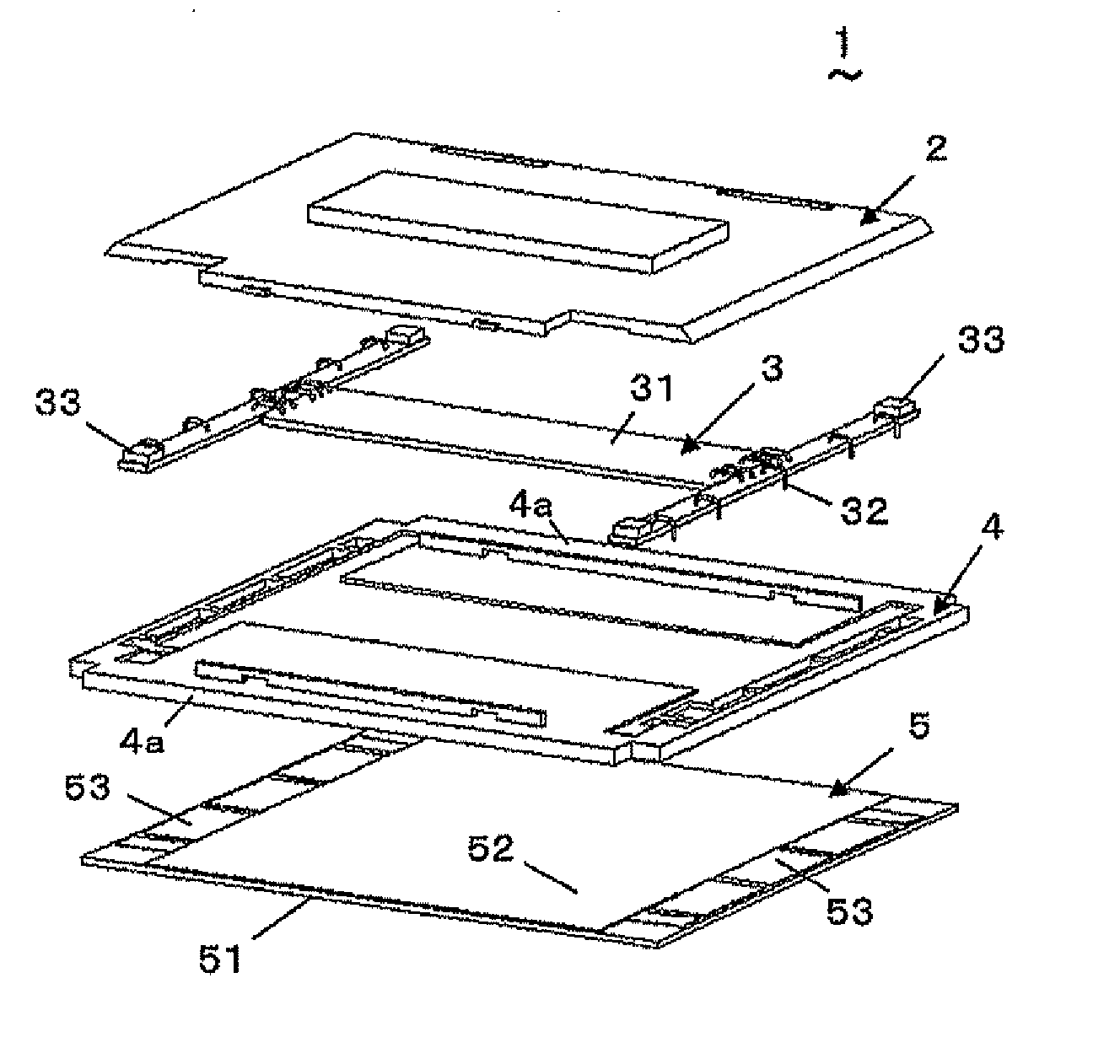
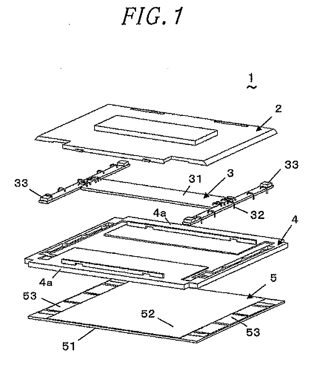
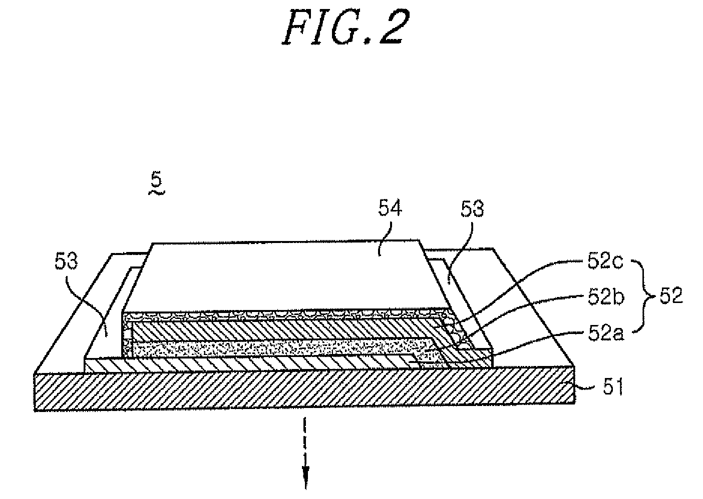
[0028]An organic EL module 1 is formed by accommodating in a casing a combined structure of a thin organic EL panel 5 and a circuit substrate 3 having power supply elements such as a power distribution pattern and the like in order to easily handle the organic EL panel or facilitates supply of power from the outside. Specifically, the organic EL module 1 of the first embodiment includes a cover 2, the circuit substrate 3, the casing 4 and the organic EL panel 5, as shown in FIG. 1.

[0029]The cover 2 is insertion-fitted to the casing 4. The circuit substrate 3 is formed by connecting three long substrates in an H-shape when viewed from the top. A power circuit 31 is provided at a central substrate of the circuit substrate 3, and connectors 33 are respectively provided at four end portions of both outer substrates of the circuit substrate 3. The power circuit 31 and the connectors 33 are electrically connected to each other by wiring patterns formed on the substrates and wirings such a...

second embodiment

[0042]An organic EL module in accordance with a second embodiment of the present invention will be described with reference to FIG. 7. As shown in FIG. 7, in an organic EL module 9, extended portions 10a are formed at the side surfaces of the casing 4 where the electrode terminals 53 of the organic EL panel 5 are not disposed over the entire length thereof. Accordingly, a length a of the long sides of the organic EL panel 5 becomes equal to a width b of the casing 4, and the organic EL module 9 has a substantially square shape when viewed from the top.

[0043]In the organic EL module 9 of the second embodiment, the damages to the wirings 32 or the contamination of the organic EL panel 5 with fingerprints can be prevented. Besides, the design feature is improved because a plurality of organic EL modules 9 arranged in the illumination device has a substantially square shape when viewed from the top.

third embodiment

[0044]An organic EL module 11 in accordance with a third embodiment of the present invention will be described with reference to FIGS. 8 and 9. As shown in FIG. 8, extended portions 12a having a predetermined width are formed at both end portions of each side surface of a casing 12 where the electrode terminals 53 of the organic EL panel 5 are not disposed 2. The length (l1+l2) of the extended portions 12a along the long sides of the organic EL panel 5 is shorter than the entire length a of the long sides of the organic EL panel 5.

[0045]As shown in FIG. 9, by combining the organic EL module 11 and the organic EL module 13 of the first embodiment, the extended portions 12a and 14a can be engaged with each other like a puzzle, and the positioning of a plurality of organic EL modules can be facilitated.

[0046]As described above, in the organic EL module 11 of the third embodiment, the extended portions 12a can serve as handle portions used for an operator to handle the organic EL module...


PUM


Abstract

An organic EL light emitting module includes an organic EL light emitting panel 5 including an organic EL light emitting unit 52 formed on a substrate 51 and electrode terminals 53 for supplying power to the organic EL light emitting unit 52; a circuit substrate 3, electrically connected to the electrode terminals 53, for supplying power to the electrode terminals 53; and a casing 4 to which the organic EL light emitting panel 5 and the circuit substrate 3 are attached. The electrode terminals 53 are disposed at left and right end portions of the organic EL light emitting panel 5 having a substantially rectangular shape when viewed from the top, and extended portions 4a protruding by a predetermined width are formed at side surfaces of the casing 4 where the electrode terminals 53 of the organic EL light emitting panel 5 are absent.

Description

FIELD OF THE INVENTION[0001]The present invention relates to an organic electroluminescence (EL) module having a light emitting unit using an organic EL light emitting device.BACKGROUND OF THE INVENTION[0002]Conventionally, there has been known an organic EL panel (see, e.g., Japanese Patent Application Publication No. 2003-257617) having as a light source a thin-type organic EL light emitting device with high brightness and a wide viewing angle. The organic EL panel is formed by laminating, on a transparent glass substrate, an anode electrode layer that is a transparent electrode made of ITO (Indium Tin Oxide) or the like, a light emitting layer made of an organic compound, and a cathode electrode layer that is a metal electrode. In the organic EL panel described in Japanese Patent Application Publication No. 2003-257617, a solution containing an organic EL material is sprayed on a rectangular substrate, and an organic EL substrate on which a group of organic EL devices is arranged...

Claims


Application Information

Patent Timeline
IPC IPC(8): H01J1/02H05B44/00
CPCH05B33/0896F21Y2115/15H05B45/60Y02B20/30H10K59/18H10K50/84H10K50/88
Inventor FUKANO, SATOSHIKAWACHI, HIDEHARUSUMIYAMA, SHIGETSUGU
Owner PANASONIC CORP
Learn More