Antenna Duplexer with High GPS Suppression

a duplexer and high gps technology, applied in the field of duplexers with high gps suppression, can solve the problems of high broadband suppression levels, low insertion losses, and difficult simultaneous compliance with all the requirements stated above, and achieve the effect of increasing suppression and reducing insertion losses

Active Publication Date: 2011-10-13
SNAPTRACK
View PDF12 Cites 13 Cited by
  • Summary
  • Abstract
  • Description
  • Claims
  • Application Information

AI Technical Summary

Benefits of technology

[0016]In one aspect, the present invention specifies an antenna duplexer which, in comparison to known duplexer circuits, has a reduced insertion loss in the transmission band and, at the same time, increased suppression in other frequency ranges, in particular of transmission si

Problems solved by technology

For antenna duplexers in the mobile radio bands in the 2 GHz range (for example, Bands I, II, III, IV or VII), simultaneous compliance with all the requirements stated above is more difficult than in the 1 GHz range.
For SAW components, it is not possible to use solely a DMS filter structure (double mode SAW), which leads to low insertion losses and high broadband suppression levels even while away from the pass band frequencies, for the transmission filter, because DMS structures do not have the required power handling capability, in particular in the 2 GHz range.
However, the use of the ladder-type structure for the transmission filter fundamentally has the disadvantage that the transmission filter therefore has in

Method used


Image

  • Antenna Duplexer with High GPS Suppression
  • Antenna Duplexer with High GPS Suppression
  • Antenna Duplexer with High GPS Suppression

Examples


Embodiment Construction

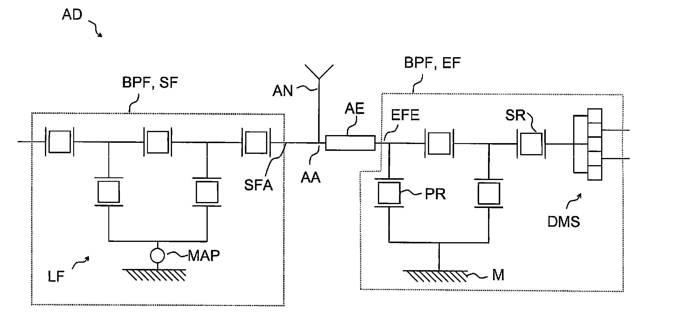
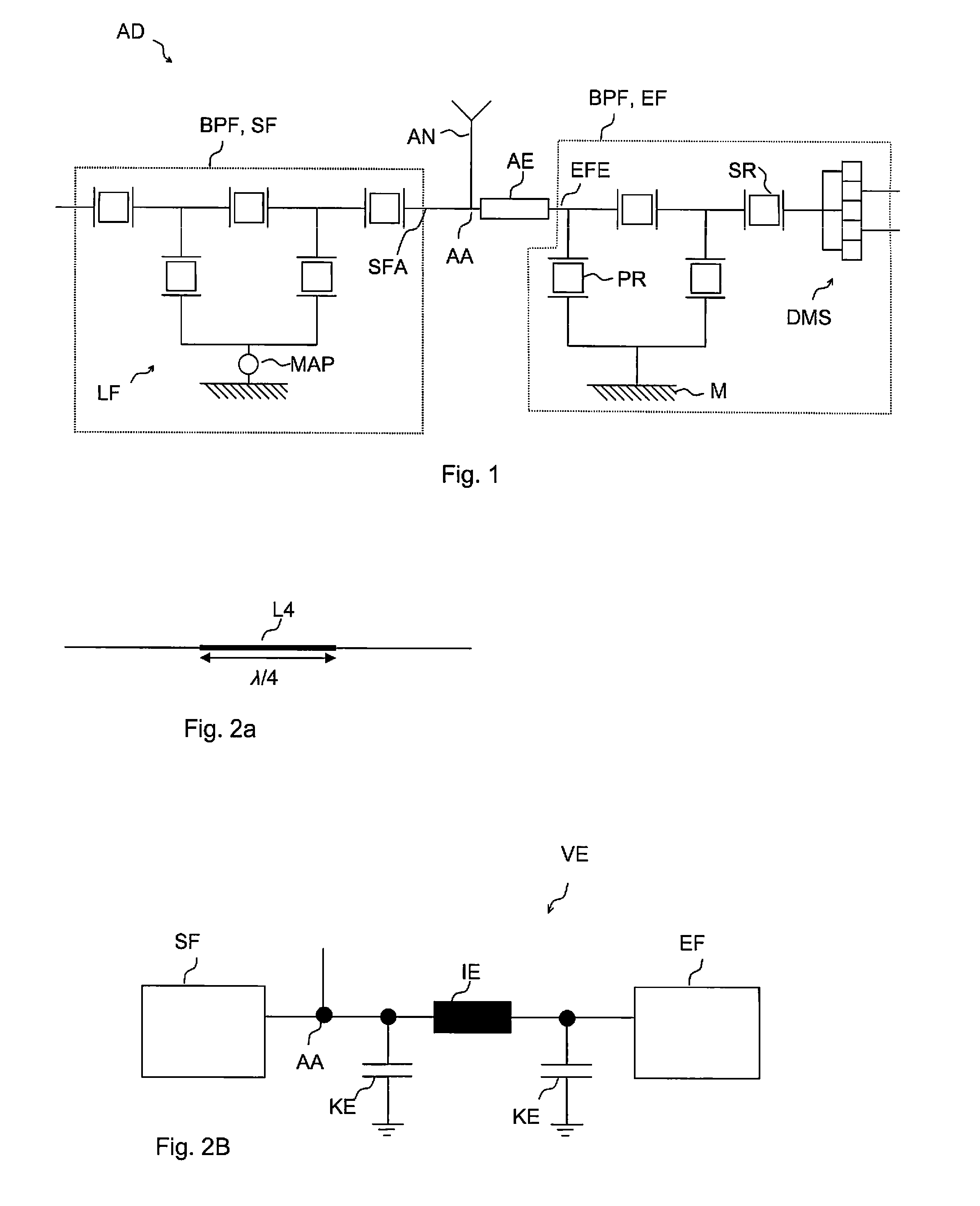
[0082]FIG. 1 shows one possible configuration of the antenna duplexer AD. A matching element AE is connected between a transmission filter output SFA and a reception filter input EFE. A signal line is connected between the transmission filter output SFA and the matching element AE to an antenna connection AA, which is electrically conductively connected to an antenna AN. Both the transmission filter SF and the reception filter EF consist of bandpass filters BPF, which each comprise a ladder-type filter structure LF. On the output side, the reception filter EF additionally has a DMS filter DMS. The first element on the input side in the reception filter EF is a parallel resonator PR, which connects the reception filter input EFE to ground M. An indication is provided in the transmission filter SF of how two different parallel resonators are connected to a joint ground pad MAP which is electrically conductively connected to ground. This ground pad MAP is arranged on the piezoelectric ...


PUM


Abstract

An antenna duplexer includes a transmission filter which operates in a transmission frequency band and has a transmission filter output. A reception filter operates in a reception frequency band and has a reception filter output. An antenna connection is connected to the transmission filter output and a matching element is connected between the antenna connection and the reception filter input. The circuit formed from the transmission filter, reception filter and matching element attenuates transmission signals in a frequency band whose frequencies f are in the interval 0.50*f0<=f<=0.75*f0, where f0 is the mid-frequency of the reception frequency band.

Description

[0001]This patent application is a national phase filing under section 371 of PCT / EP2009 / 063510, filed Oct. 15, 2009, which claims the priority of German patent application 10 2008 052 222.8, filed Oct. 17, 2008, each of which is incorporated herein by reference in its entirety.TECHNICAL FIELD[0002]The invention relates to an antenna duplexer with high suppression in the GPS frequency band.BACKGROUND[0003]Duplexers, which are used, for example, in portable communication appliances, on the one hand have the purpose of passing on transmission signals from transmission paths to an antenna connection without them being passed into reception paths, which are intended for received signals and have sensitive low-noise amplifiers. This means that duplexers thus must have the capability to carry a large amount of power in the transmission path at the transmission frequencies and, ideally, a low insertion loss in the pass band, since this is the only way to achieve a communication appliance w...

Claims


Application Information

Patent Timeline
IPC IPC(8): H03H9/70H03H9/64
CPCH03H9/725H03H9/706
Inventor KLAMM, HELMUTSELMEIER, PETER
Owner SNAPTRACK
Why Eureka
Try Eureka