Liquid crystal display, system and method for displaying three-dimensional stereo pictures

a liquid crystal display and three-dimensional stereo technology, applied in the field of video displays, can solve the problems of reducing the resolution of the image, taking a long time to finish the alternation, and affecting the effect of the effect of the alternation

Active Publication Date: 2011-10-13
NVIDIA CORP
View PDF18 Cites 47 Cited by
  • Summary
  • Abstract
  • Description
  • Claims
  • Application Information

AI Technical Summary

Benefits of technology

[0010]According to another aspect of the present invention, a method for displaying three-dimensional stereo pictures is provided. The method comprises the steps of controlling a left-eye image and a right-eye image to be displayed on a liquid crystal displays (LCD) alternately, said LCD comprises a backlight source, and a first polarizer, a first liquid crystal panel, a second polarizer and a second liquid crystal panel sequentially arranged on said backlight source; controlling said second liquid crystal panel in such a way that the polarizing angle of the light traveling through and exiting from said second liquid crystal panel is switched between a horizontal and vertical polarization.

Problems solved by technology

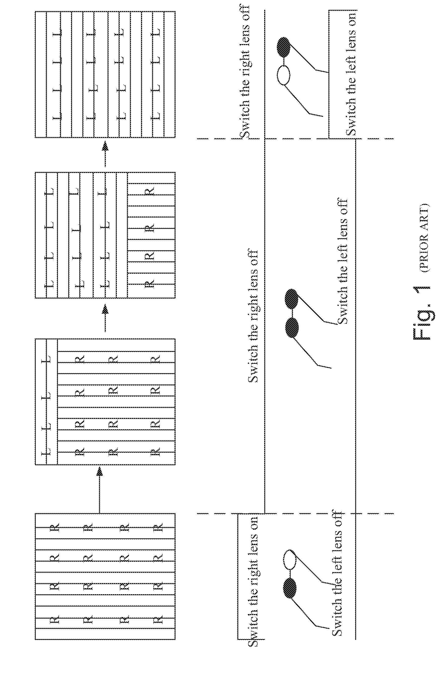
However, the disadvantages of this technology is in that it will take some time to finish the alternation of the left-eye image and the right-eye image since the image is displayed row by row, and it will lead that a part of the right-eye image and a part of the left-eye image are displayed on the monitor at the same time.
The closing of the shading glasses will result in that the image which people see becomes dark.
There are also some disadvantages of this technology.
As a result, a display and method for displaying stereo images which will not decrease the resolution of the image and have sufficient displaying luminance is needed.

Method used


Image

  • Liquid crystal display, system and method for displaying three-dimensional stereo pictures
  • Liquid crystal display, system and method for displaying three-dimensional stereo pictures
  • Liquid crystal display, system and method for displaying three-dimensional stereo pictures

Examples


exemplary embodiment 1

[0028]As shown in FIG. 3, as an example, the polarization direction of the first polarizer 302 is horizontal, the polarization direction of the second polarizer 304 is vertical, the second liquid crystal panel 305 is TN liquid crystal panel, the polarization direction of the left lens is horizontal, and the right lens is vertical. The changing process of the polarization direction of the light passing through the first polarizer 302, the first liquid crystal panel 303, the second polarizer 304 and the second liquid crystal panel 305 sequentially will be interpreted as below.

[0029]The left-eye image is displayed at first. The polarization direction of the light for the left-eye image will become horizontal after passing through the first polarizer 302. The signal sent from the GPU controls the electrical field applied on the first liquid crystal panel 303, and the liquid crystal molecules twist from 0 degree to 90 degree. Due to that the polarized plane of the incident light will def...

exemplary embodiment 2

[0032]As another example, the polarization direction of the first polarizer 302 is horizontal, the polarization direction of the second polarizer 304 is vertical, the second liquid crystal panel 305 is STN liquid crystal panel, the polarization direction of the left lens is vertical, and the right lens is horizontal. The changing process of the polarization direction of the light passing through the first polarizer 302, the first liquid crystal panel 303, the second polarizer 304 and the second liquid crystal panel 305 sequentially will be interpreted as below.

[0033]The left-eye image is displayed at first. The polarization direction of the light for the left-eye image will become horizontal after passing through the first polarizer 302. The signal sent from the GPU controls the electrical field applied on the first liquid crystal panel 303, and the liquid crystal molecules twist from 0 degree to 90 degree. Due to that the polarized plane of the incident light will deflect along wit...

exemplary embodiment 3

[0036]Still as another example, the polarization direction of the first polarizer 302 is horizontal, the polarization direction of the second polarizer 304 is vertical, the second liquid crystal panel 305 is TN liquid crystal panel, the polarization direction of the left lens is vertical, and the right lens is horizontal. The changing process of the polarization direction of the light passing through the first polarizer 302, the first liquid crystal panel 303, the second polarizer 304 and the second liquid crystal panel 305 sequentially will be interpreted as below.

[0037]The left-eye image is displayed at first. The polarization direction of the light for the left eye image will become horizontal after passing through the first polarizer 302. The signal sent from the GPU controls the electrical field applied on the first liquid crystal panel 303, and the liquid crystal molecules twist from 0 degree to 90 degree. Due to that the polarized plane of the incident light will deflect alon...


PUM


Abstract

A three-dimensional stereo display, and a system and method are provided for controlling the three-dimensional stereo display. The three-dimensional stereo display includes backlight, a first polarizer, a first liquid crystal panel, a second polarizer and a second liquid crystal panel which are sequentially arranged on the backlight source. The second liquid crystal panel switches the polarizing angle of the light travelling through and exiting from said second liquid crystal panel between a horizontal and vertical polarization. Due to the polarization direction of light could be changed by the liquid crystal panel, and makes the light for the left-eye image and the right-eye image are mutual perpendicular. The polarization direction of the light for the left-eye image is the same as that of the left lens, and the polarization direction of the light for the right-eye image is the same as that of the right lens. So the light belongs to the left-eye image or the right-eye image can pass through the left lens or the right lens respectively, then a stereo image will emerge in people's brain due to the effect of “fusion activity”. Further, there is no need to close the polarized spectacles, the displaying efficiency is improved compared with the “Active Stereo”.

Description

CLAIM OF PRIORITY[0001]The present application claims the priority of Chinese Patent Application No. 201010144797A filed Apr. 12, 2010, which is incorporated herein by reference.FIELD OF INVENTION[0002]The present invention relates to video displays, and more particularly to liquid crystal display, system and method for displaying three-dimensional stereo pictures.BACKGROUND OF THE INVENTION[0003]With the development of the technology of three-dimensional (3D) stereo display, 3D stereo displays are used in many fields, such as mobile communication terminals, TV, computer, Car Monitor and so on. 3D application will enter people's daily life more deeply. The mechanism of seeing 3D) stereo image by human eyes is in that everything seen by the left eye and right eye respectively is different in angle because there is a distance between the left eye and right eye. So there will be a little difference in the images caught by the left eye and right eye respectively, which is called “parall...

Claims


Application Information

Patent Timeline
Patent Type & Authority Applications(United States)
IPC IPC(8): G06T15/00G02B30/25
CPCG02B27/2242G02B27/26H04N13/0497H04N13/0438G02F1/13471G02B30/25G02B30/36H04N13/341H04N13/398
Inventor XU, SHUANG
Owner NVIDIA CORP
Why Eureka
Try Eureka