Fiber optic security mat system

a fiber optic and mat technology, applied in the field of security monitoring, can solve the problem of insufficiently sensitive over the surface of the mat to avoid, and achieve the effects of complete emi immunity, low cost, and easy installation

Inactive Publication Date: 2011-10-13
CLEVELAND ELECTRIC LAB
View PDF8 Cites 16 Cited by
  • Summary
  • Abstract
  • Description
  • Claims
  • Application Information

AI Technical Summary

Benefits of technology

[0013]According to another embodiment, a method of assembling a strain sensing device includes the steps of: attaching an optical fiber to a middle layer so that any strain created by an associated load and experienced by the first layer is transmitted to the optical fiber; attaching a top layer to a bottom layer along an outside edge substantially encapsulating the first layer between the second and third layers; and connecting the optical fiber to an associated signal processing system for measuring the strain created by the associated load. The method can further include the steps of evacuation of at least a portion of any volume between the layers to minimize any air between the layers and thereby preventing ballooning effects from thermal expansion of the air. The method can further includes the steps of evacuating the air located between the top and bottom layers before substantially sealing the middle layer between the top and bottom layers. The method can further includes the steps of applying a frictional coating between the top and middle layers and between the middle and bottom layers before substantially sealing the middle layer between the top and bottom layers. The method can further includes the steps of inserting an additional layer between the top and bottom layers before substantially sealing the additional and middle layers between the top and bottom layers.
[0016]Another advantage of several of the embodiments of this invention is substantial independence of mat properties from sensing properties, thereby allowing the choice of mat materials to be optimized for other properties, such as resilience, fire safety, wear resistance, and pedestrian slip resistance.
[0018]Yet another advantage of this invention is the small size and ultimate simplicity of fiber Bragg gratings and optical fibers. For example, if single-mode fibers and gratings are used, buffered single-mode optical fibers and integral fiber Bragg gratings are only about 0.9 mm in diameter. Unbuffered single-mode optical fibers and integral fiber Bragg gratings are only 0.25 mm or less in diameter. These parts can be installed easily, inexpensively, and almost seamlessly into the assembled security mat sensing device, which is necessarily thin for practical purposes. This invention can include the use of multi-mode fibers.
[0019]Yet another advantage of this invention is the low cost of a multiplicity of fiber Bragg gratings on the same fiber when manufactured continuously on the single fiber as draw-tower gratings, which are well known in the art. A potentially even greater cost advantage is realized, at least with larger systems, when distributed sensing technology is used instead of fiber Bragg grating technology.
[0020]Yet another advantage of this invention is the ability of optical fibers to transmit signals over long distances (as far as several kilometers) with negligible loss.
[0021]Yet another advantage of this invention is the ability to incorporate and interrogate many sensors—or sensor regions in the case of distributed sensing technology—on a single optical fiber. This multiplexing ability greatly simplifies cabling and measurement instrumentation.

Problems solved by technology

However, the fiber optic security mat devices with which the inventors are familiar have not worked well, having only spotty detection capability, They are therefore insufficiently sensitive over the surface of the mat to avoid false negatives, thereby missing the presence of an offending object or person in some areas of the mat.

Method used


Image

  • Fiber optic security mat system
  • Fiber optic security mat system
  • Fiber optic security mat system

Examples


first embodiment

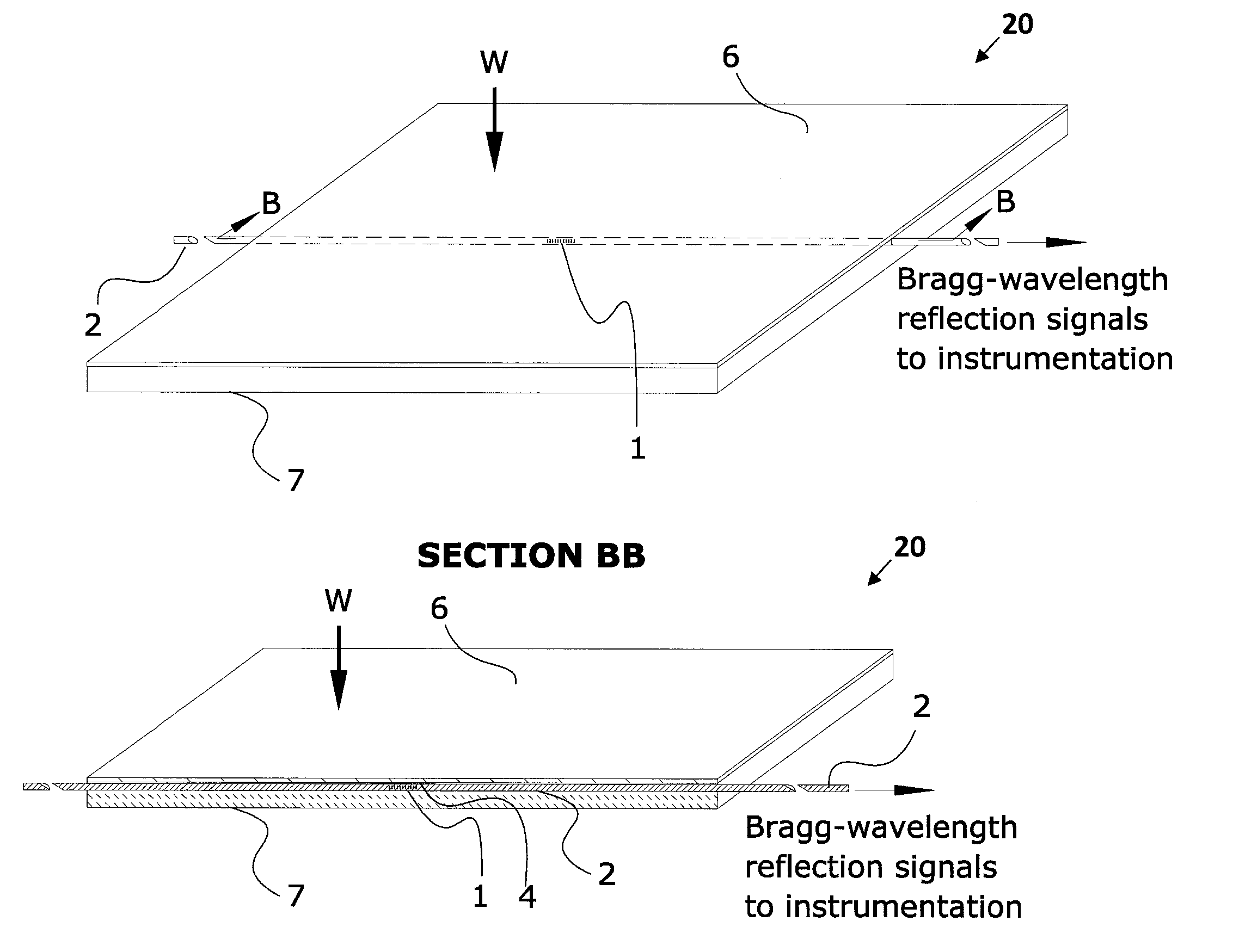
[0060]According to this invention, the security mat sensing device of the security system can include the following five mutually bonded layers, listed from top to bottom:

[0061]The first layer can include an elastomeric or plastic mat, such as a mat designed to carry foot traffic, of sufficient durometer and thickness to resist puncture and wear, yet with sufficient flexibility to transmit load to the layers below.

[0062]The second layer can include an upper thin compliant layer of highly resilient material such as elastomer foam to substantially decouple mat properties from the adjacent strain sensor assembly and thereby transmit substantially vertical loads to the membrane strain sensor assembly below.

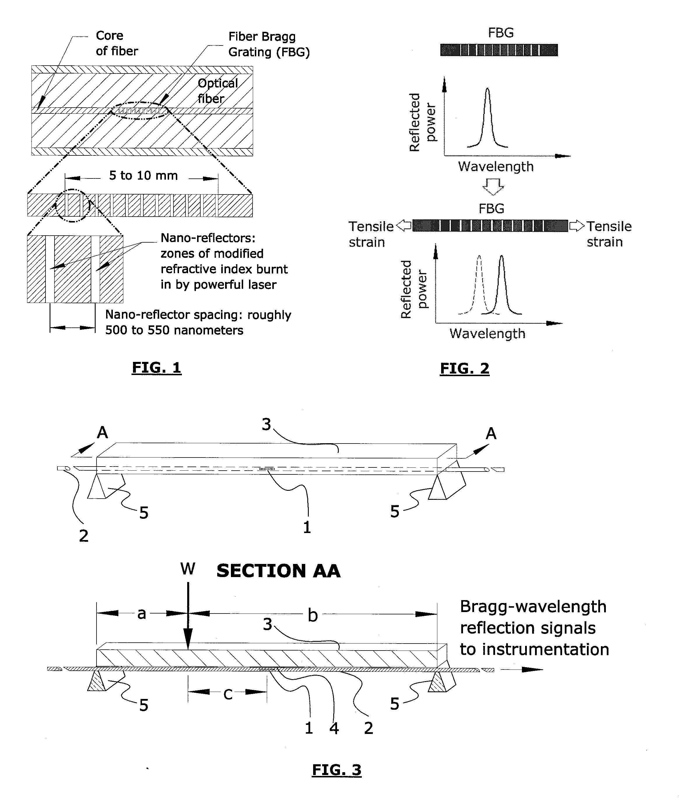
[0063]The third layer can include a membrane strain sensor assembly, which includes a plurality of unbuffered fiber Bragg gratings (FBGs), as well as their immediately adjacent short sections of fiber, bonded at strategic locations to the underside of a polymer, composite, or metallic...

tenth embodiment

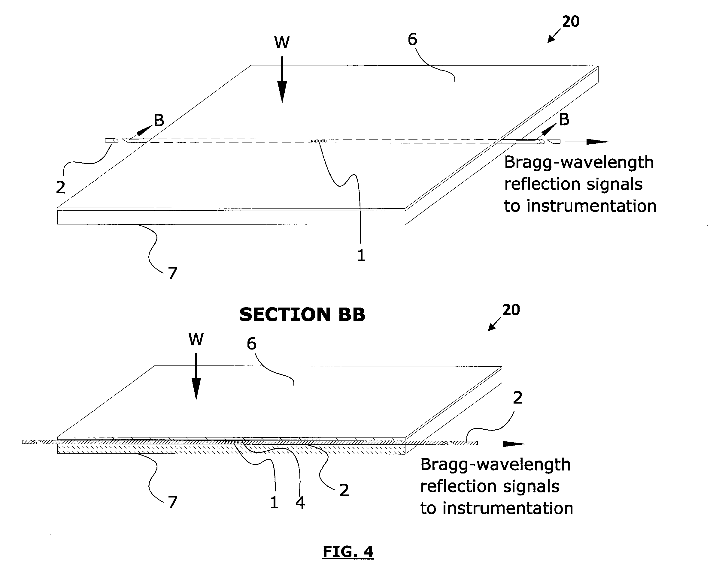
[0075] the security mat sensing device of the security system includes the following mutually bonded three layers, listed from top to bottom:

[0076]A first layer can include combination polymer-membrane and mat strain sensor assembly, which includes a plurality of buffered or unbuffered fiber Bragg gratings (FBGs), as well as their immediately adjacent short sections of fiber, bonded at strategic locations to the underside of a polymer sheet that functions both as a mat—such as a mat designed to carry foot traffic—and as a mechanical membrane. The combination membrane and mat has sufficient modulus and thickness to transmit strains from incident loads anywhere on its upper surface to one or more of the fiber Bragg gratings on its lower surface, so as to cause readily measurable shifts in fiber Bragg grating characteristic reflected Bragg wavelengths. However, the combination membrane and mat must not be so thin as to transmit strain inadequately and be damaged easily, and not so thic...

eleventh embodiment

[0079]According to an eleventh embodiment, the security mat sensing device of the security system includes the following mutually bonded two layers, listed from top to bottom:

[0080]The first layer can include the first layer, or combination polymer-membrane and mat strain sensor assembly, of the tenth embodiment; and

[0081]The second layer can include a bottom compliant layer having a density, compressive modulus, resilience, and thickness that allows the membrane strain sensor assembly to flex and recover sufficiently to transmit strain to the fiber Bragg gratings. Additionally, this compliant layer is supportive enough to prevent damage to the membrane strain sensor assembly when the mat layer is subjected to foreseeable loads. The compliant layer is also strong enough to protect the upper layers from damage and provides a surface that resists sliding or can be bonded to a variety of substrates. In some embodiments, a soft elastomeric polymer, such as low durometer neoprene, would ...


PUM

PropertyMeasurementUnit
diameteraaaaaaaaaa
diameteraaaaaaaaaa
metallicaaaaaaaaaa

Abstract

A sensing device includes a first layer, a second layer, and an optical sensor. The first layer includes a first surface for supporting an associated load. The first layer transmits a strain to a second surface due to the associated load located on the first surface. The second layer is formed of a compliant material and provides substantially uniform support to the first layer and deflects due to the associated load. The optical sensor is positioned between the first and second layers and senses the strain due to the associated load.

Description

CROSS-REFERENCE TO RELATED APPLICATIONS[0001]This application claims the benefit of U.S. Provisional Application No. 61 / 312,909, titled FIBER OPTIC SECURITY MAT SYSTEM, filed Mar. 11, 2010, which is herein incorporated by reference.STATEMENT REGARDING FEDERALLY SPONSORED RESEARCH OR DEVELOPMENT[0002]Not Applicable.THE NAMES OF THE PARTIES TO A JOINT RESEARCH AGREEMENT[0003]Not Applicable.INCORPORATION-BY-REFERENCE OF MATERIAL SUBMITTED ON A COMPACT DISC[0004]Not Applicable.BACKGROUND OF THE INVENTION[0005]1. Field of the Invention[0006]This invention relates generally to security monitoring and particularly with regard to detecting the undesired, unlawful, or hazardous presence of persons, objects, or vehicles.[0007]2. Description of Related Art[0008]The present art includes various technologies that detect or attempt to detect the undesired, unlawful, or hazardous presence of persons, objects, or vehicles. Such detection has become especially necessary with the recent increase in i...

Claims


Application Information

Patent Timeline
Patent Type & Authority Applications(United States)
IPC IPC(8): G01B11/16B23P11/00
CPCY10T29/49826G01B11/18
Inventor LANTZ, JOELMCNEILLY, MICHAEL
Owner CLEVELAND ELECTRIC LAB
Why Eureka
Try Eureka