Compensating optical coupler for visible and nir imaging

a technology of optical couplers and optical couplers, applied in the field of compensating optical couplers for visible and nir imaging, can solve the problem that conventional optical instruments are not compatible with such imaging systems

Active Publication Date: 2011-10-13
STRYKER EUROPEAN OPERATIONS LIMITED
View PDF5 Cites 63 Cited by
  • Summary
  • Abstract
  • Description
  • Claims
  • Application Information

AI Technical Summary

Benefits of technology

[0005]The disclosed system utilizes a combination of correction mechanisms in a novel optical coupler to address the multiple challenges in compensating for the NIR imaging properties of conventional optical instruments without degrading the performance in the visible spectrum. Specifically, this VIS NIR optical coupler splits the optical path into visible and NIR paths within th

Problems solved by technology

This is particularly problematic for imaging systems using a single color image sensor onto which both visible light and NIR light images are pro

Method used


Image

  • Compensating optical coupler for visible and nir imaging
  • Compensating optical coupler for visible and nir imaging
  • Compensating optical coupler for visible and nir imaging

Examples


Embodiment Construction

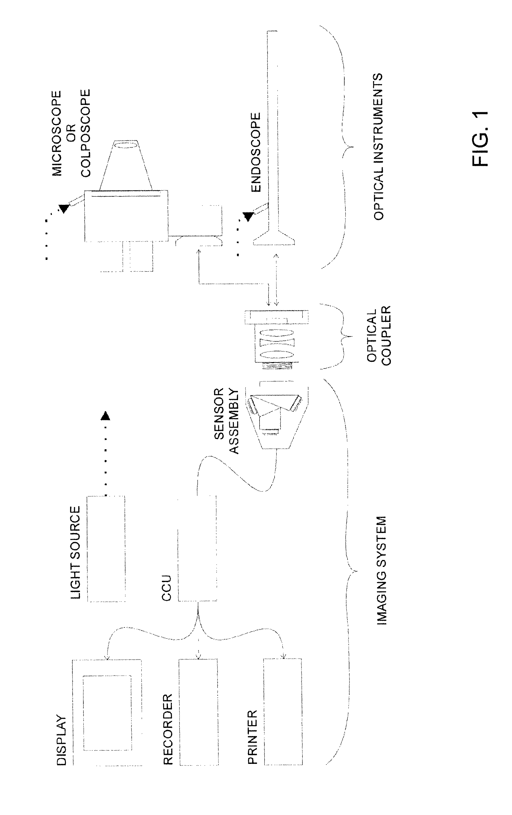
[0013]FIG. 1 depicts a typical configuration of an optical instrument, optical coupler and imaging system. The components may include an optical instrument such as the endoscope shown or another optical image transmitting instrument such as a microscope, a colposcope, or the like. The optical instrument is connected to the imaging system by an optical coupler that projects an optical image from the optical instrument onto the imaging system's sensor assembly. The sensor assembly may be a single or multi-sensor (e.g. 3-chip) assembly composed of CCD or CMOS or other solid state image sensors. The sensor assembly converts the optical image into electrical signals which may subsequently be processed and outputted to a display, recording and / or printing device.

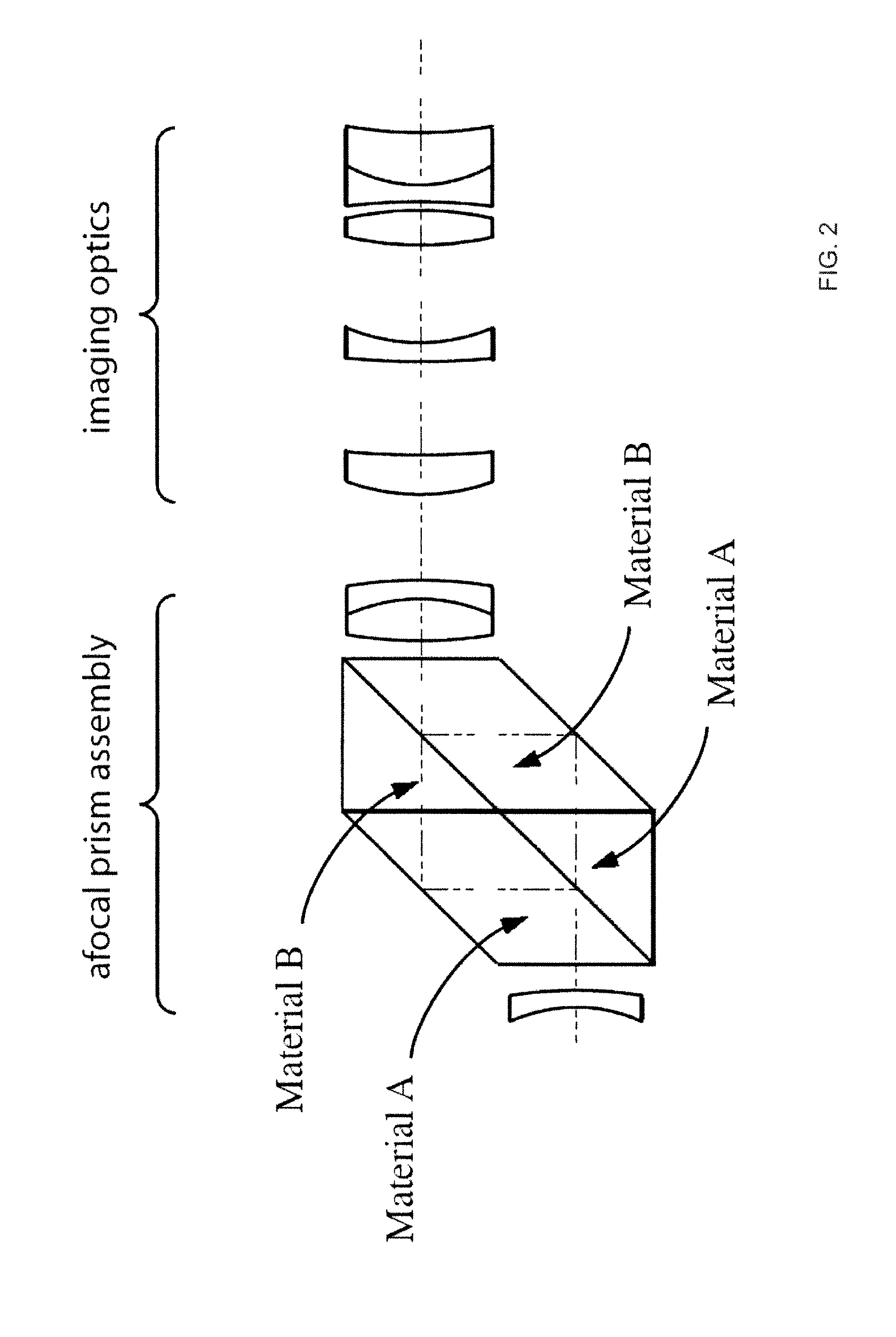
[0014]The conventional optical coupler used with visible light imaging systems typically consists of a multi-element lens assembly with either a fixed or adjustable focus. More sophisticated couplers may incorporate zoom lens desi...


PUM


Abstract

An optical system, in particular for endoscopic applications, is disclosed which uses wavelength-compensating optical components, in particular prisms, made of materials with different inter-element coatings and refractive indices to image significantly different wavelength-ranges (VIS and NIR) onto the same image plane of an image acquisition device, such as a CCD sensor.

Description

BACKGROUND[0001]Near-infrared (NIR) imaging using endoscopes has been described in the literature for various clinical applications. Typically, such an imaging modality utilizes a contrast agent (e.g. indocyanine green) that absorbs and / or fluoresces in the 700-900 nm range of the NIR. In some endoscopic imaging systems capable of high resolution simultaneous color and NIR imaging, none of the image sensors (if multiple image sensors are used) or specific pixels of an image sensor (if only a single color image sensor is used) are exclusively dedicated to NIR imaging. One exemplary imaging system, described in the Annex of the present disclosure, utilizes a red, green, blue (RGB) sensor assembly to acquire both color and NIR fluorescence images by employing the red image sensor to, alternately and in rapid succession, acquire both the red light required for the color image and NIR light required for the NIR image. This imaging system is intended to be used in conjunction with image-p...

Claims


Application Information

Patent Timeline
IPC IPC(8): G02B13/14G02B27/10
CPCA61B1/042A61B5/0075A61B5/0086G01J3/36G02B27/141G02B23/2484G02B13/146A61B1/00126G02B27/0025G02B23/2453G01J3/32
Inventor TESAR, JOHN C.COTTLE, PAULFENGLER, JOHN J.P.
Owner STRYKER EUROPEAN OPERATIONS LIMITED
Why Eureka
Try Eureka