
Sound perception using frequency transposition by moving the envelope

a frequency transposition and envelope technology, applied in the direction of electrical transducers, tone control, enclosures/cabinets/supports, etc., can solve the problems of sound quality degradation and severely limit the flexibility of the system, so as to improve speech intelligibility, improve user's perception of input sound, and increase sound quality

Active Publication Date: 2011-10-13
OTICON
View PDF5 Cites 50 Cited by
  • Summary
  • Abstract
  • Description
  • Claims
  • Application Information

AI Technical Summary

Benefits of technology

[0015]An object of the present application is to increase the sound quality of a sound signal as perceived by a user, e.g. a hearing impaired user. A further object is to improve speech intelligibility, e.g. in frequency lowering systems. A further object is to increase the possibilities of providing an appropriate fitting for different types of hearing impairment. A further object is to improve the sound perception of an audio signal transmitted and received via a transmission channel.
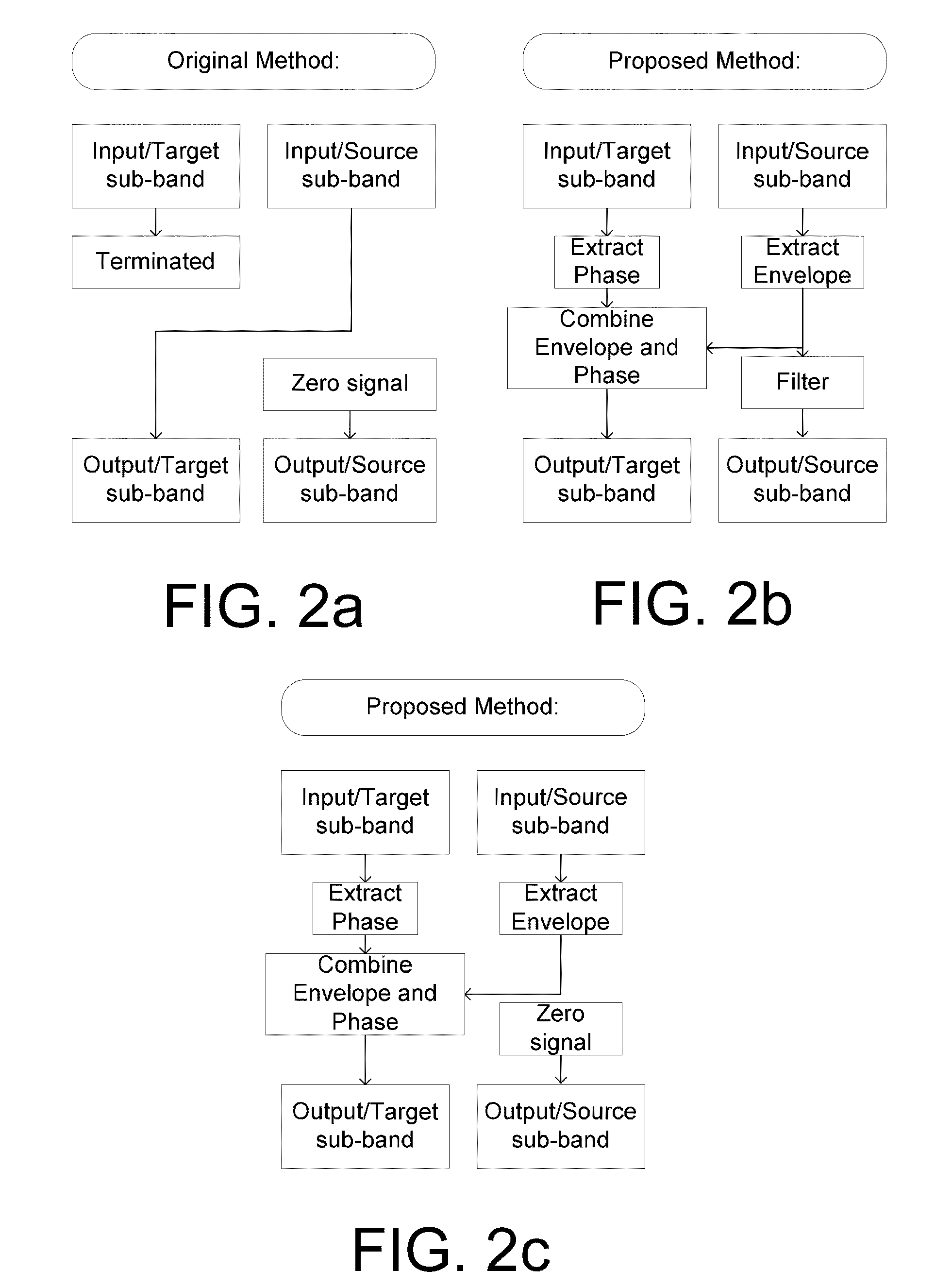
[0018]An object of the application is achieved by a method of improving a user's perception of an input sound. The method comprises,a) Defining a critical frequency fcrit between a low frequency range and a high frequency range;b) Analyzing an input sound in a number of frequency bands below and above said critical frequency;c) Defining a cut-off frequency fcut below said critical frequency fcrit;d) Identifying a source frequency band above said cut-off frequency fcut;e) Extracting the envelope of said source band;f) Identifying a corresponding target band below said critical frequency fcrit;g) Extracting the phase of said target band;h) Combining the envelope of said source band with the phase of said target band.
[0019]This has the advantage of increasing the sound quality, and the potential to further improve speech intelligibility in frequency transposition, e.g. frequency lowering systems.
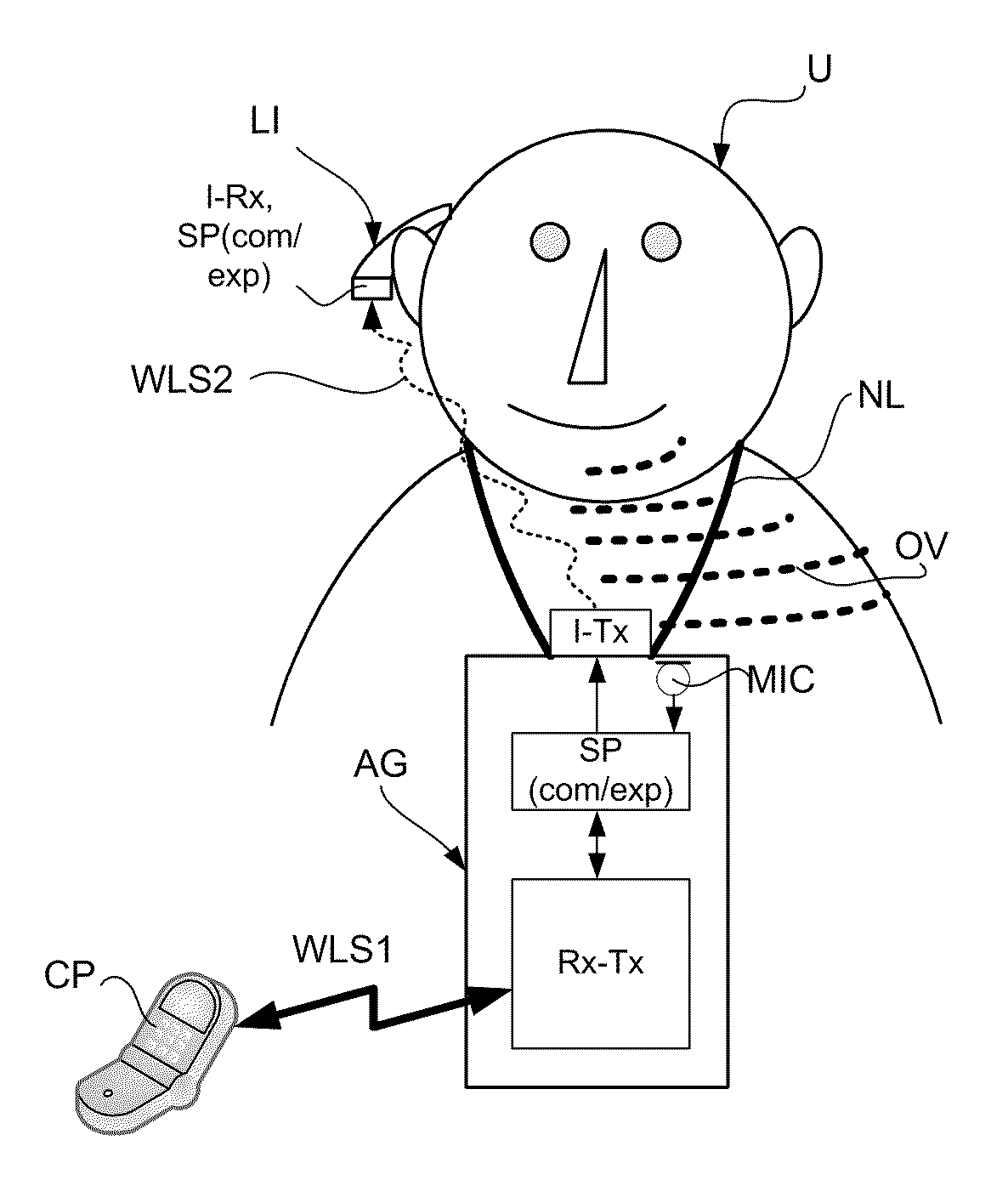
[0036]In an embodiment, the method comprises compressing the frequency range of an audio signal above a cut-off frequency with a predefined compression function (e.g. a predefined compression ratio) adapted to a specific transmission channel and transmitting the compressed signal via the transmission channel. In an embodiment the method further comprises receiving the transmitted signal end expanding the received signal with a predefined expansion function (e.g. a predefined compression ratio) corresponding to the compression function (e.g. being the inverse of). In the expansion process, the compressed part of the signal may be expanded by widening each compressed band to fill out the full frequency range of the original signal, each magnitude value of the compressed signal thus representing a magnitude of an expanded band. The phase values of the compressed bands may be expanded likewise. Alternatively, the phase values of the expanded bands may be synthesized (e.g. to provide a randomly distributed, or a constant phase). Alternatively, the phase information of the original signal (before compression) is coded and transmitted over the (low-bandwidth) transmission channel and used to regenerate the phase of the expanded signal. This method can e.g. be used to transmit a full bandwidth audio signal over a transmission channel having a reduced bandwidth thereby saving transmission bandwidth (and power) or improving the sound perception of a signal transmitted over a fixed bandwidth channel, e.g. a telephone channel. This has the potential of improving sound quality, and possibly speech intelligibility in case the signal is a speech signal (e.g. of a telephone conversation).An Audio Processing Device:

Problems solved by technology

This causes sound quality degradations and severely limits the flexibility of the system.

Method used


Image

  • Sound perception using frequency transposition by moving the envelope
  • Sound perception using frequency transposition by moving the envelope
  • Sound perception using frequency transposition by moving the envelope

Examples


Embodiment Construction

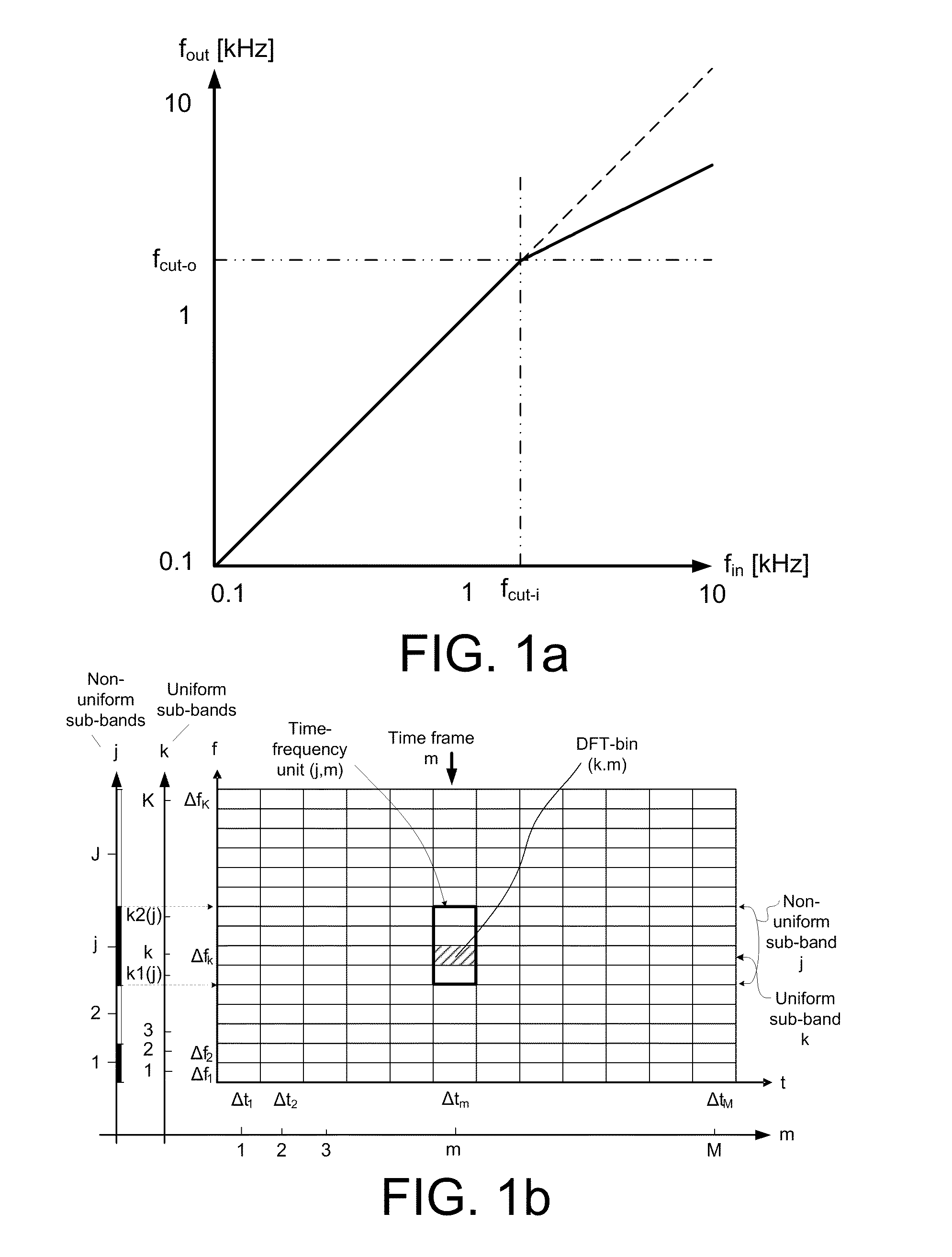
[0070]FIG. 1a shows a simple frequency compression scheme for an audio signal for converting an input frequency range (here 0.1 kHz to 10 kHz) to an (compressed) output frequency range (here 0.1 kHz to approximately 2.5 kHz). The frequency compression scheme comprises a non-compressed (linear, fin=fout) part and a compressed (fin>fout) part at frequencies, respectively, below and above a predetermined cut-off frequency, fcut-i (here approximately 1.5 kHz and equal to fcut-o).

[0071]In a particular embodiment, a time-frequency representation s(k,m) of a signal s(n) comprises values of magnitude and phase of the signal in a number of DFT-bins (DFT=Direct Fourier Transform) defined by indices (k,m), where k=1, . . . , K represents a number K of frequency values and m=1, . . . , M represents a number M of time frames, a time frame being defined by a specific time index m and the corresponding K DFT-bins. This corresponds to a uni-form frequency band representation, each band comprising a...


PUM


Abstract

The application relates to a method of improving a user's perception of an input sound. The application further relates to an audio processing device and to its use. The object of the present application is to increase the sound quality of a sound signal as perceived by a user, e.g. a hearing impaired user. The method comprises a) Defining a critical frequency fcrit between a low frequency range and a high frequency range; b) Analyzing an input sound in a number of frequency bands below and above said critical frequency; c) Defining a cut-off frequency fcut below said critical frequency fcrit; d) Identifying a source frequency band above said cut-off frequency fcut; e) Extracting the envelope of said source band; f) Identifying a corresponding target band below said critical frequency fcrit; g) Extracting the phase of said target band; h) Combining the envelope of said source band with the phase of said target band. This has the advantage of increasing the sound quality, and the potential to further improve speech intelligibility in frequency transposition, e.g. frequency lowering systems. The invention may e.g. be used in communication devices, such as telephones, or listening devices, e.g. hearing instruments, headsets, head phones, active ear protection devices or combinations thereof.

Description

TECHNICAL FIELD[0001]The present application relates to improvements in sound perception, e.g. speech intelligibility, in particular to improving sound perception for a person, e.g. a hearing impaired person. The disclosure relates specifically to a method of improving a user's perception of an input sound.[0002]The application furthermore relates to an audio processing device and to its use.[0003]The application further relates to a data processing system comprising a processor and program code means for causing the processor to perform at least some of the steps of the method and to a computer readable medium storing the program code means.[0004]The disclosure may e.g. be useful in applications such as communication devices, e.g. telephones, or listening devices, e.g. hearing instruments, headsets, head phones, active ear protection devices or combinations thereof.BACKGROUND ART[0005]The following account of the prior art relates to one of the areas of application of the present a...

Claims


Application Information

Patent Timeline
Patent Type & Authority Applications(United States)
IPC IPC(8): H04R25/00H03G5/00
CPCH04R25/353H04R25/407H04R2225/43
Inventor HOLMBERG, MARCUSKAULBERG, THOMASDE HAAN, JAN MARK
Owner OTICON
Learn More