Method and arrangement for removing solid particles and tar component from carbon monoxide gas

a carbon monoxide gas and solid particle technology, applied in the field of method and arrangement for removing solid particle and tar component can solve the problem that coal dust cannot be fed, and achieve the effect of efficient separation from carbon monoxide gas

a carbon monoxide gas and solid particle technology, applied in the field of method and arrangement for removing solid particle and tar component can solve the problem that coal dust cannot be fed, and achieve the effect of efficient separation from carbon monoxide gas

US20110252967A1Active Publication Date: 2011-10-20METSO OUTOTEC (FINLAND) OY

Image

  • Method and arrangement for removing solid particles and tar component from carbon monoxide gas
  • Method and arrangement for removing solid particles and tar component from carbon monoxide gas

Examples


Embodiment Construction

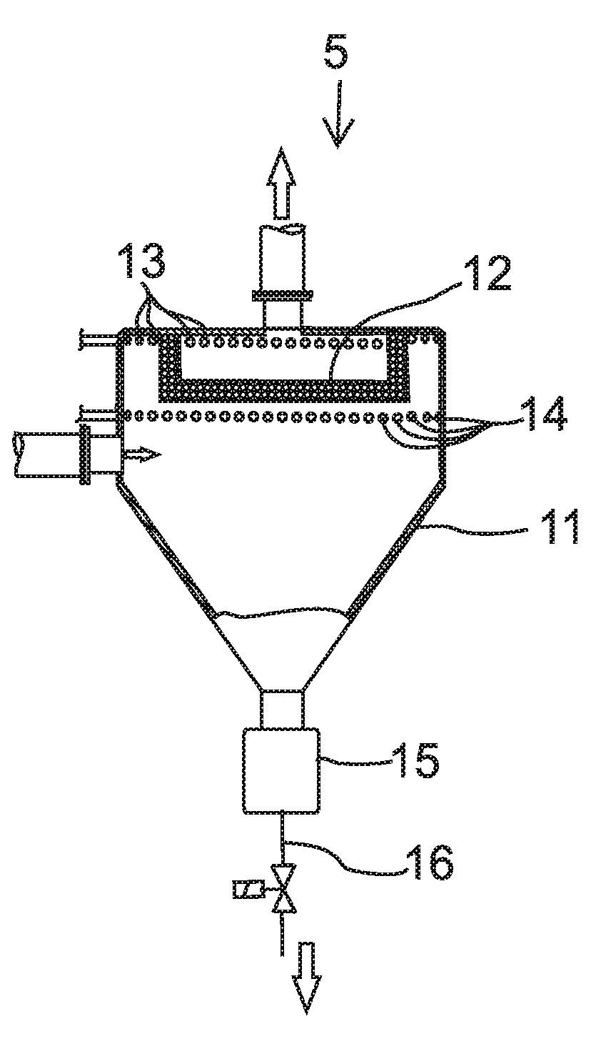
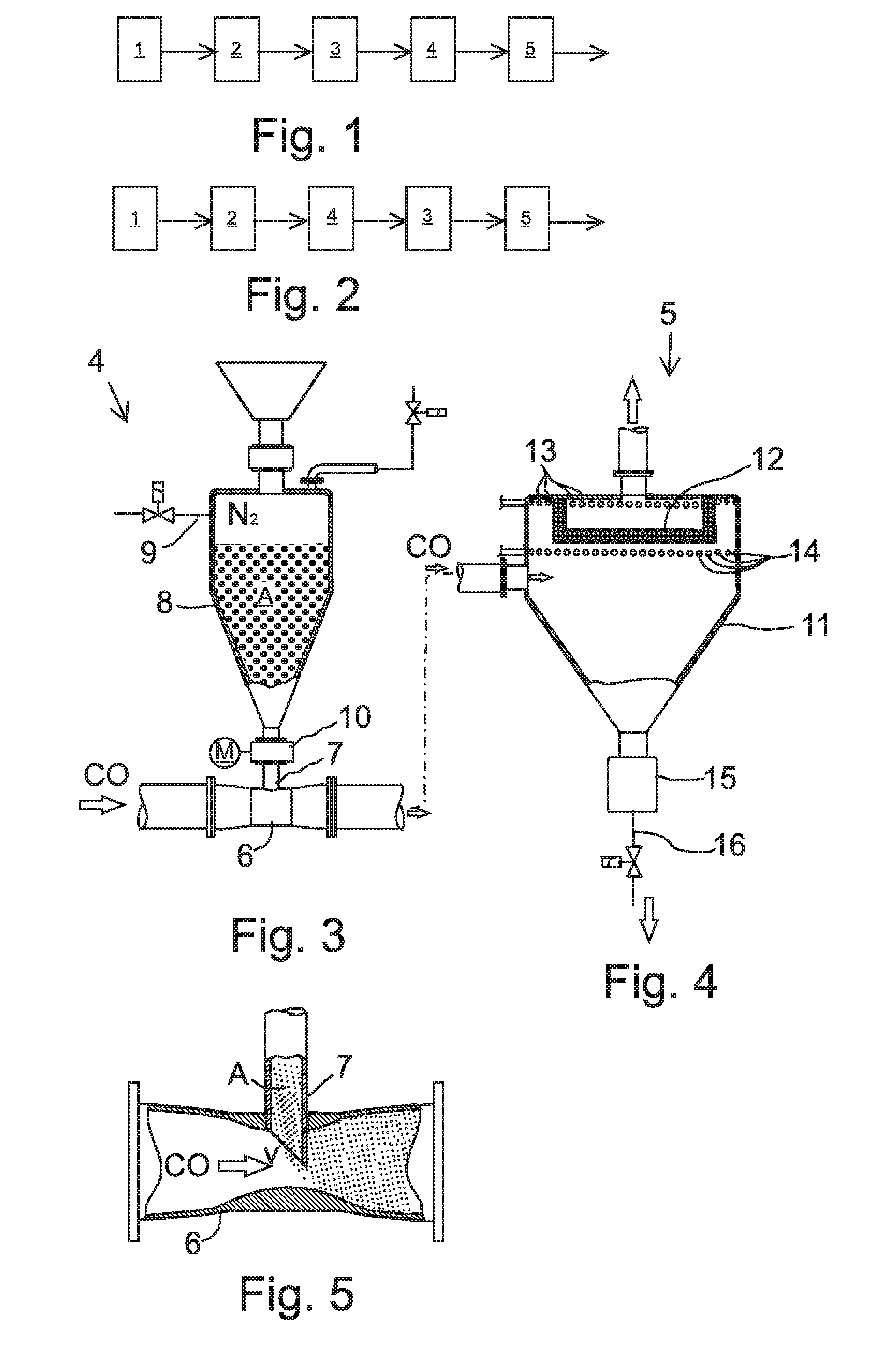
[0034]FIG. 1 is a schematical illustration of a process, by which solid particles and volatile tar component are removed from the carbon monoxide gas created in a ferroalloy smelting furnace 1. From the metal smelting furnace 1, the carbon monoxide gas is conducted to a gas scrubber 2, which can be a conventional venturi scrubber, where carbon monoxide gas is scrubbed by spraying it with a liquid medium, such as water, so that part of the solid particles is discharged along with the water. Then the carbon monoxide gas is conducted from the gas scrubber 2 to a blower 3, by which the flow rate of the carbon monoxide gas is increased. Thereafter the carbon monoxide gas is conducted to a particle feeder 4, where finely divided adsorbent particles are fed in the carbon monoxide gas in order to make the tar component stick on the surface of the adsorbent particles, and the carbon monoxide gas flow containing adsorbent particles is conducted to a particulate filter 5, in which the tar comp...


PUM

PropertyMeasurementUnit
Grain sizeaaaaaaaaaa
Fractionaaaaaaaaaa
Speedaaaaaaaaaa

Abstract

A method and arrangement for removing solid particles and tar component from carbon monoxide gas. In the method, carbon monoxide gas is conducted from a ferroalloy smelting furnace (1) to a gas scrubber (2), the carbon monoxide gas is scrubbed in the gas scrubber (2) by a liquid medium for removing part of the solid particles, the carbon monoxide gas is conducted from the gas scrubber to a blower (3), the flow rate of the carbon monoxide gas is increased by the blower (3), and the carbon monoxide gas is conducted to a particulate filter (5) and the remaining solid particles are essentially filtered in the particulate filter (5) from the carbon monoxide gas. Prior to conducting the carbon monoxide gas to the particulate filter (5), it is conducted to a particle feeder (4), where finely divided adsorbent particles (A) are fed in the carbon monoxide gas for adhering the tar component on the surface of the adsorbent particles, and the carbon monoxide gas flow containing adsorbent particles is conducted to the particulate filter (5), in which case the tar component adhered on the adsorbent particles is discharged in the particulate filter (5).

Description

FIELD OF INVENTION[0001]The invention relates to a method defined in the preamble of claim 1. The invention also relates to an arrangement defined in the preamble of claim 8.BACKGROUND OF INVENTION[0002]The invention relates to metal smelting processes, such as ferrochromium smelting, which is generally carried out in a submerged-arc furnace. The operation of a submerged-arc furnace is based on conducting electric current between electrodes through the material to be smelted. The electric resistance of the material to be smelted generates thermal energy, so that the batch is heated, when a high electric current is conducted through the material to be smelted. The current is transferred to vertically positioned electrodes, which are located symmetrically in a triangle with respect to the furnace center point. When necessary, the positioning depth of the electrodes in the furnace is adjusted, because they are worn at the tips. The electrodes extend to the inside of the furnace via thr...

Claims


Application Information

Patent Timeline
20 Oct 2011
Publication
US20110252967A1
IPC
B01D50/00; B01D53/14; B01D53/02
CPC
B01D46/0068; B01D47/06; B01D50/006; C10K1/101; C10K1/024; C10K1/08; B01D51/04; B01D53/10
Inventors
RONNBERG, TOM; HAJEK, STEFAN