
Blade Arrangement For A Food Processing Vat

Active Publication Date: 2011-10-20
CHEESE SYST
View PDF13 Cites 1 Cited by
  • Summary
  • Abstract
  • Description
  • Claims
  • Application Information

AI Technical Summary

Benefits of technology

[0008]In accordance with an aspect of the invention, a food processing vat is provided with blade assemblies mounted on two horizontal shafts that define a common swept volume between them. Blade assemblies of the two shafts simultaneously move through the common volume, working the contents from both sides of the vat. This may enhance stirring or cutting of the contents by imparting a turbulent flow of the contents in the common volume which may ensure that the contents and blade assemblies are moving at least somewhat in different directions.
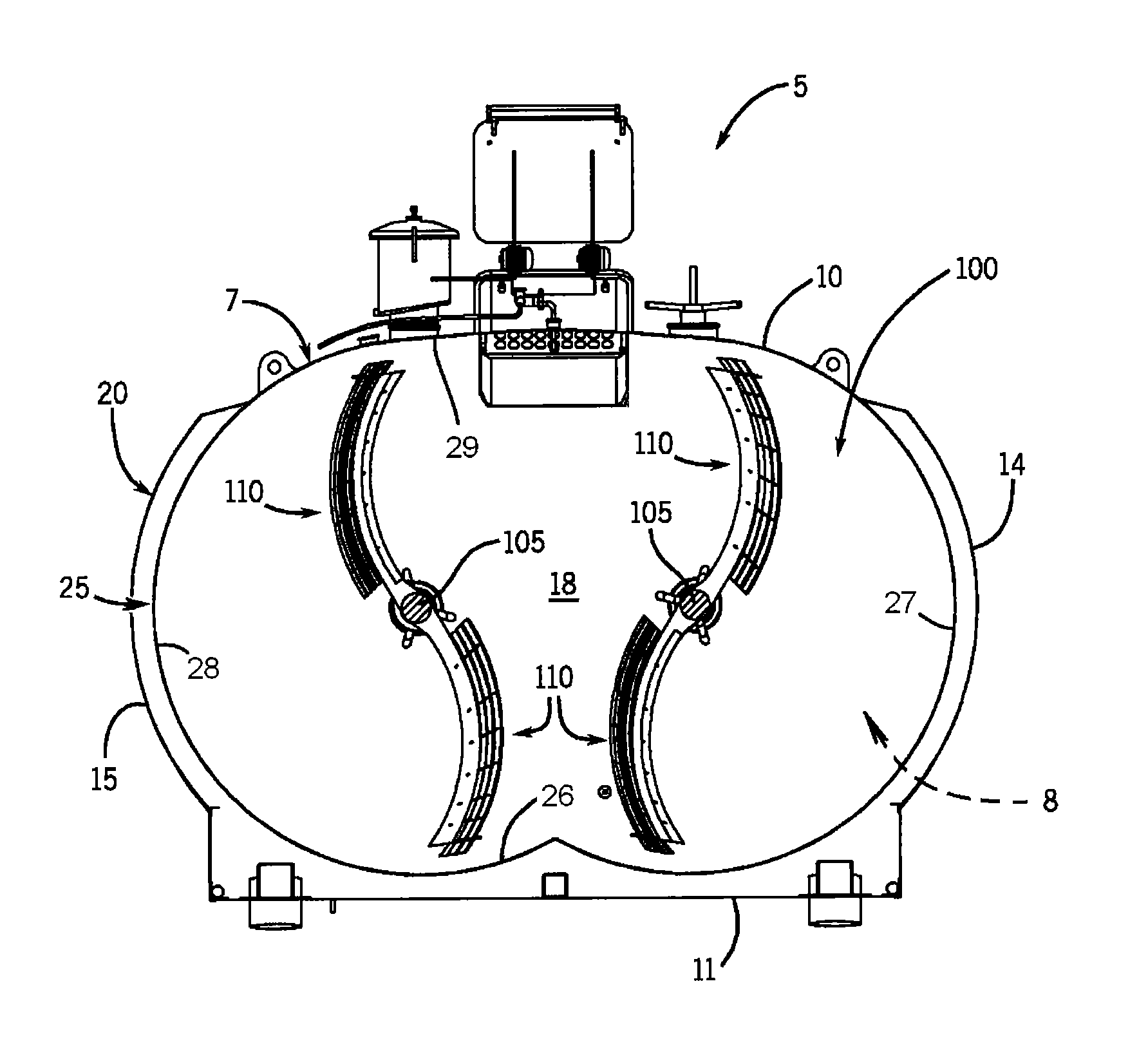
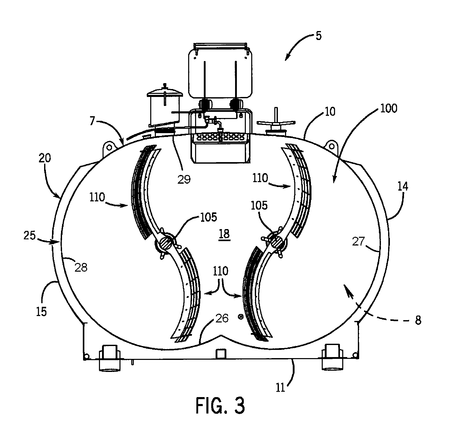
[0009]In accordance with another aspect of the invention, the blade assemblies define curved baskets and each shaft may include multiple curved baskets extending from it. Adjacent curved baskets on one shaft may be spaced from each other and in staggered alignment with corresponding spaced-apart curved baskets on the other shaft. This allows the multiple curved baskets of the pair of shafts to intermesh and simultaneously pass through the common volume between the shafts, whether the shafts rotate in the same or opposite directions, which may impart a cutting or stirring action that enhances turbulent flow of the vat contents in the common volume.
[0010]In accordance with another aspect of the invention, the blade assemblies extend generally in an axial direction away from the respective shafts. Each blade assembly faces different directions at different locations along its length. In this way, even if the vat contents and a blade assembly as a whole are moving in the same direction, since different portions of the blade assembly face different directions, the contents may be contacted by the different portions of the blade assembly in at least angularly different directions, which enhances cutting or stirring. Centrifugally flowing vat contents may encounter a portion of the blade assembly that faces angularly toward the shaft, such that the contents centrifugally flow in a direction which may be closer to normal with respect to that portion of blade assembly than tangential. This may enhance the cutting or stirring of the vat contents because the contents may be centrifugally forced through the blade assembly instead of sliding along it.
[0011]In accordance with another aspect of the invention, the blade assemblies have curved knives with different portions that face different directions along the length of the curved knives. The curved knives may cumulatively define a curved basket. The curved basket may be curved longitudinally and transversely so that it has a dished-in or concave side and an opposing dished-out or convex side. The longitudinal and transverse curvatures may be provided by curved longitudinal knives and curved transverse knives, respectively, of the curved basket. The curved baskets may enhance the cutting or stirring of the vat contents because the contents may be centrifugally forced through the curved basket instead of sliding along it.
[0012]In accordance with another aspect of the invention, a food processing vat is provided with blade assemblies that extend in opposing directions from the shaft(s). This may improve the rotational balance of the shaft(s) which may extend the use-life of bearings, bushings, and / or other shaft supporting structures.
[0013]In accordance with another aspect of the invention, the knife assemblies define curved baskets that extend in opposite directions, with respect to each other, from the shaft(s). The curved baskets may be mounted so that those extending in one direction are positioned as a result of a double reflection, a horizontal and a vertical reflection about the shaft when the shaft is viewed from an end view, with respect to the curved baskets extending in the opposite direction. The curved baskets that extend in opposite directions from the shaft, when viewed from an end view of the shaft, may define an S-shaped or sigmoidal profile so that their weights are substantially symmetrical about a centerline of the shaft. This may improve the rotational balance of the shaft during use.

Problems solved by technology

The inventors have recognized that the centrifugal flow component imparts movement of the contents a direction that is tangential with the cutting or stirring surfaces of the flat-panel agitator, whereby the contents may at least partially slide outwardly along the flat-panel agitators, which may reduce the efficiency of the cutting or stirring.
The inventors have also recognized that in typical vats, the agitators extend from a single side of or in substantially a single direction from the shafts and that this may cause rotational imbalances during use.

Method used


Image

  • Blade Arrangement For A Food Processing Vat
  • Blade Arrangement For A Food Processing Vat
  • Blade Arrangement For A Food Processing Vat

Examples


Embodiment Construction

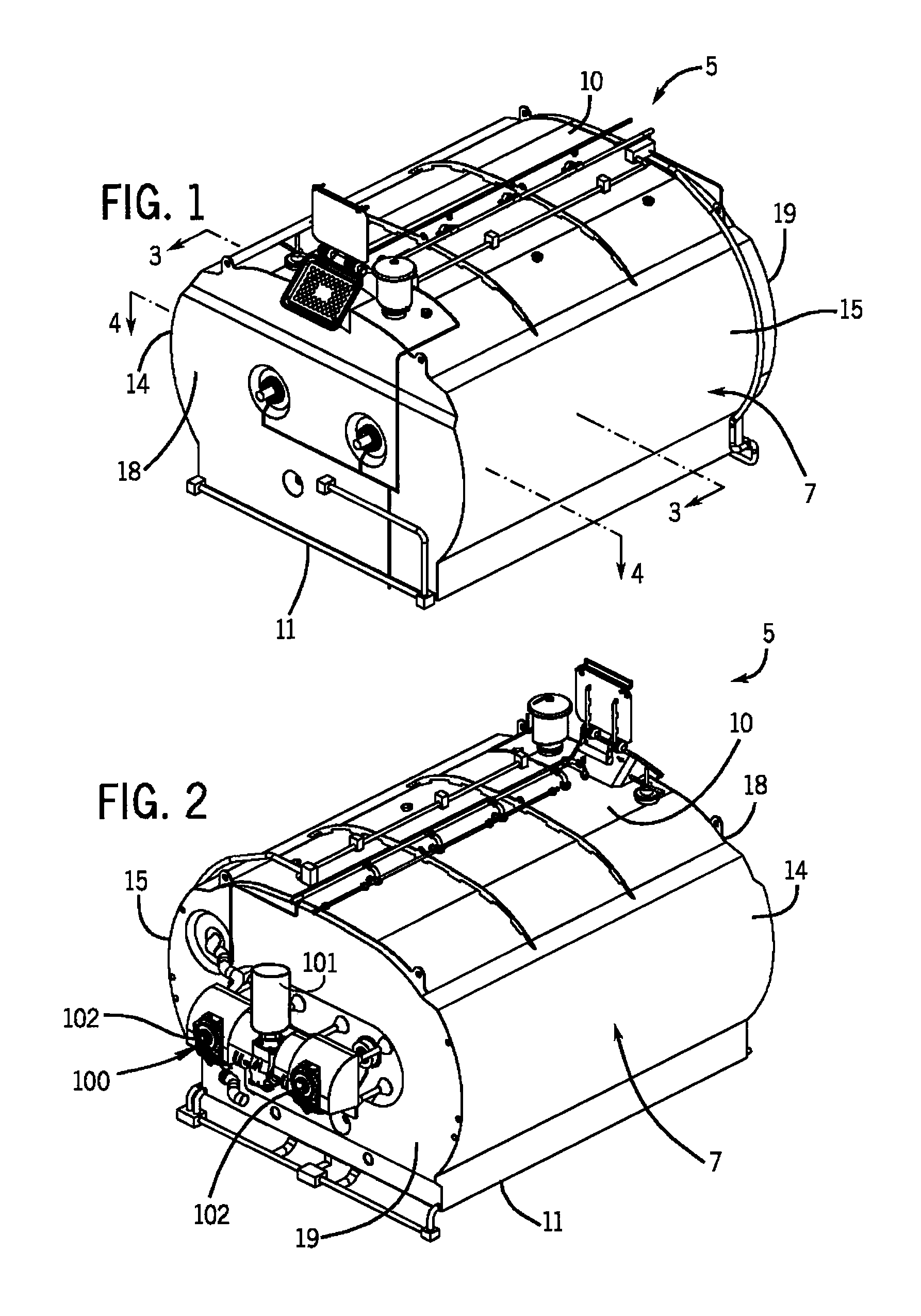
[0032]FIGS. 1 and 2 illustrate a vat system 5 that can be used for processing food and related products (collectively referred to as “vat contents”) by mechanically manipulating and heating or cooling the vat contents, depending on the particular food or related product being processed. In a representative application, the vat system 5 may be used in the production of cheese, although it is understood that the vat system 5 may be used in processing other types of food products. The system 5 includes a vat 7 that has a heat transferring system to perform such heating and cooling, and an agitation system 100 (FIG. 2) that performs the mechanical manipulations tasks.

[0033]Referring now to FIGS. 1-4, vat 7 defines an enclosure having a top wall 10, a bottom wall 11, and side walls 14, 15, all of which extend longitudinally between a pair of end walls 18 and 19 (FIGS. 1 and 3). The walls 10, 11, 14, are 15 are multilayered, having an outer jacket 20 and an inner shell 25 that are spaced ...


PUM


Abstract

A food processing vat is provided with blade assemblies that extend from opposing sides of a rotating shaft. The blade assemblies may be curved or otherwise face different directions at different locations along their respective lengths. The vat may have a pair of rotating shafts and the rotation of the shafts may be timed so that the blade assemblies of the shafts simultaneously travel through a common swept volume. The blade assemblies may be positioned on the shafts so that they intermesh through each other while simultaneously moving through the common volume.

Description

CROSS-REFERENCE TO RELATED APPLICATIONS[0001]This application claims priority from U.S. Provisional Patent Application Ser. No. 61 / 325,612 filed on Apr. 19, 2010, the entirety of which is expressly incorporated by reference herein.BACKGROUND OF THE INVENTION[0002]1. Field of the Invention[0003]The invention relates to food processing vats and, more particularly, to agitation and cutting systems of food processing vats.[0004]2. Discussion of the Related Art[0005]Agitation and cutting systems for use in food processing vats are known in the food processing industries. Such systems are widely used in equipment for processing semi-liquid food products, such as cheese vats.[0006]Agitation and cutting systems used in cheese vats typically have panels mounted on and rotating with shafts. The panels have sharp edges on one surface and dull edges on an opposing surface. This allows the panels to rotate in the direction(s) that the sharp edges face to cut the contents of the food processing v...

Claims


Application Information

Patent Timeline
IPC IPC(8): A01J25/00
CPCA01J25/06B01F7/00275B01F15/00714B01F7/042B01F7/00283B01F27/1123B01F27/1124B01F27/702B01F35/4122B01F2101/06A47J43/044A47J43/0711
Inventor ISENBERG, TIMOTHY J.ZIRBEL, JOHN E.
Owner CHEESE SYST
Learn More