Inert gas fire-extinguishing system for reducing the risk of an extinguishing fires in a protected room

a fire-extinguishing system and inert gas technology, applied in boring tools, medical science, dentistry, etc., can solve the problems of not being able to follow a predefined sequence of events, the risk of being set at a predetermined level, and the multi-stage inert gas fire-extinguishing system does not allow. , to achieve the effect of reducing the risk of extinguishing fires, reducing the oxygen content, and reducing the risk of and

Active Publication Date: 2011-10-20
AMRONA
View PDF7 Cites 17 Cited by
  • Summary
  • Abstract
  • Description
  • Claims
  • Application Information

AI Technical Summary

Benefits of technology

[0044]Generally speaking, the invention thus also relates to an inerting method for reducing the risk of and extinguishing fires in a protected room in which an oxygen-displacing gas stored under high pressure is initially reduced to a working pressure and thereafter introduced into the protected room in order to reduce the oxygen content in the protected room to a specific lowered level, wherein a first pressure-reducing mechanism, through which the oxygen-displacing gas flows at the beginning of reducing the oxygen content, is used to reduce the pressure of the oxygen-displacing gas stored under high pressure, and wherein at least one second pressure-reducing mechanism, through which the oxygen-displacing gas does not flow until after a specific amount of time has passed since pressure reduction has begun, is used to further reduce the pressure of the oxygen-displacing gas stored to under high pressure.

Problems solved by technology

In practical use of the above-described and known per se two-stage inerting method, however, the fact that the inerting of the protected room to set a predetermined lowered level, such as, for example, the base or full inerting level, cannot ensue according to a predefined sequence of events has proven problematic in certain cases.
In particular, the currently known multi-stage inert gas fire-extinguishing systems do not allow for the fact that it might at times be desired to gradually render a protected room inert; i.e., regulating the predefined lowered to levels in progressive stages according to different sequences of events, wherein these sequences of events can be adapted to specific conditions.
Due to this limitation, an inert gas fire-extinguishing system as described, for example, in the DE 198 11 851 A1 printed publication is not suited or only conditionally suited as a multi-zone fire-extinguishing system, since inertization cannot be adapted to individual protected rooms.
When employing an inert gas fire-extinguishing system as a multi-zone system, thus, one in which one and the same inert gas fire-extinguishing system provides preventative fire control or extinguishing for a plurality of protected rooms, the problem thus, arises that regardless of which of the multiple protected rooms is to be flooded with oxygen-displacing gas, each protected room is rendered inert according to one and the same sequence of events.

Method used


Image

  • Inert gas fire-extinguishing system for reducing the risk of an extinguishing fires in a protected room
  • Inert gas fire-extinguishing system for reducing the risk of an extinguishing fires in a protected room
  • Inert gas fire-extinguishing system for reducing the risk of an extinguishing fires in a protected room

Examples


Embodiment Construction

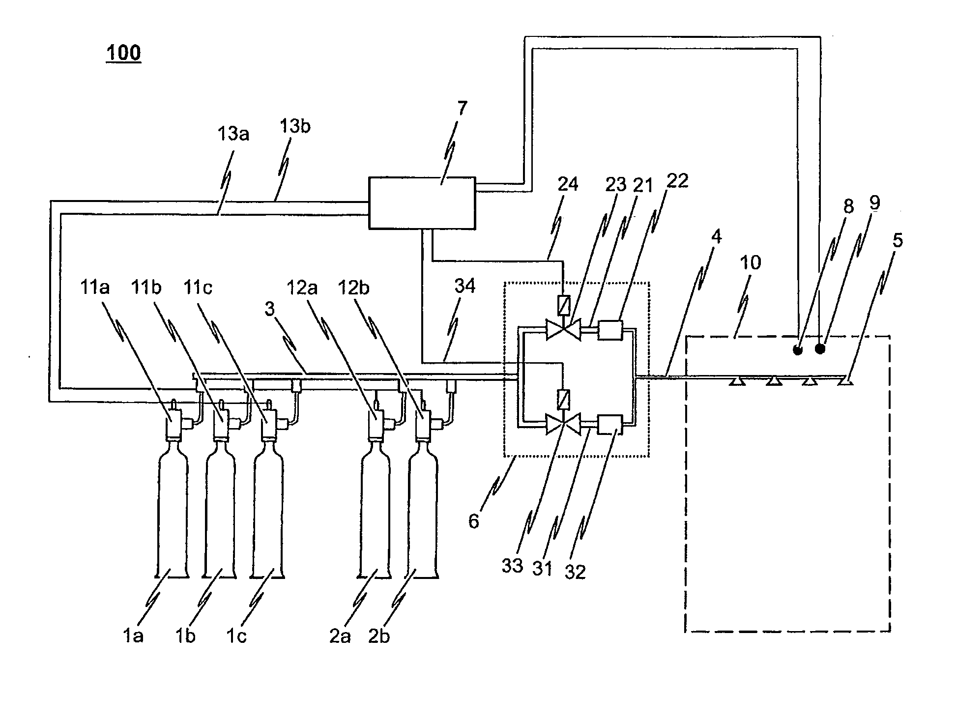
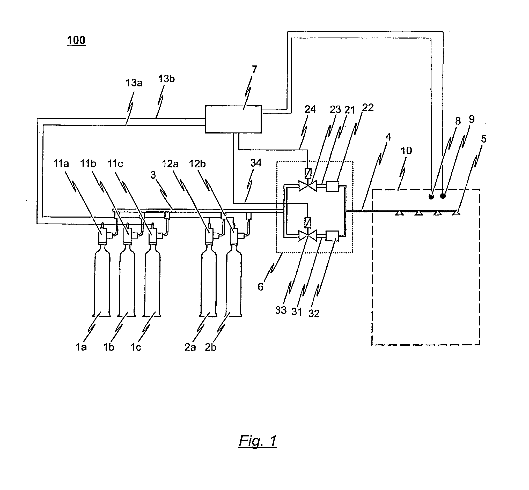
[0054]FIG. 1 shows a schematic view of a first preferred embodiment of the inventive inert gas fire-extinguishing system 100. The inert gas fire-extinguishing system 100 includes a total of five high-pressure gas tanks 1a, 1b, 1c, 2a, 2b, each realized for example as standard commercial 200-bar or 300-bar high-pressure gas cylinders. Also conceivable here would be using one or more high-pressure gas reservoirs in place of the high-pressure gas cylinders, for example, in the form of high-pressure gas storage pipes. An oxygen-displacing gas or gas mixture, consisting for example of nitrogen, carbon dioxide and / or noble gas, is stored under high pressure in the high-pressure gas tanks 1a, 1b, 1c, 2a, 2b.

[0055]In the embodiment of the inert gas fire-extinguishing system 100 as depicted, the high-pressure gas tanks 1a, 1b, 1c, 2a, 2b are divided into two groups consisting of high-pressure gas tanks 1a, 1b, 1c and high-pressure gas tanks 2a, 2b. Dividing the high-pressure gas tanks 1a, 1...


PUM


Abstract

The invention relates to an inert gas fire-extinguishing system for reducing the risk of and extinguishing fires in a protected room. So as to have the inerting of the protected room ensue according to different variable sequences of events, the inert gas fire-extinguishing system includes a pressure-reducing device having at least two parallel branches, wherein each parallel branch has a pressure-reducing mechanism. Each parallel branch is connectable to a high-pressure collecting line and a low-pressure extinguishing line via a controllable valve, whereby each pressure-reducing mechanism is designed to reduce a high input pressure to a low output pressure according to a known pressure-reducing characteristic curve.

Description

CROSS-REFERENCE TO RELATED APPLICATIONS[0001]The present invention is a 35 U.S.C. 371 National Stage Entry of PCT / EP2009 / 063019, filed Oct. 7, 2009, which claims priority from European Patent Application No. 08166037.5, filed Oct. 7, 2008, the contents of all of which are herein incorporated by reference in their entirety.BACKGROUND OF THE INVENTION[0002]1. Field of the Invention[0003]The invention relates to an inert gas fire-extinguishing system for reducing the risk of and extinguishing fires in a protected room, wherein the inert gas fire-extinguishing system includes at least one high-pressure gas tank in which an oxygen-displacing gas is stored under high pressure, wherein the high-pressure gas tank is connectable to a collecting line via a quick-opening valve; and wherein an extinguishing line is further provided which is connected on one side to the collecting line via a pressure-reducing device and on the other side to extinguishing nozzles.[0004]2. Description of the Relat...

Claims


Application Information

Patent Timeline
Patent Type & Authority Applications(United States)
IPC IPC(8): A62C2/00
CPCA62C35/68A62C99/0018A62C35/02A62C99/0027A62C35/15
Inventor CLAESSEN, THOMASWAGNER, ERNST-WERNER
Owner AMRONA
Why Eureka
Try Eureka