Molten metal leakege confinement and thernal optimization in vessels used for containing molten metal

a technology of leakage confinement and thermal optimization, which is applied in the field of vessel used for containing and/or conveying molten metals, can solve the problems of difficult installation in such a way, high cost of solving the problem of metal leakage, and damage to the heating elemen

Active Publication Date: 2011-10-20
NOVELIS INC
View PDF5 Cites 4 Cited by
  • Summary
  • Abstract
  • Description
  • Claims
  • Application Information

AI Technical Summary

Benefits of technology

An exemplary embodiment provides a vessel used for containing molten metal. The vessel includes a refractory liner having at least two refractory liner units positioned end to end, with a joint between the units, the units each having an exterior surface and a metal-contacting interior surface. The vessel also has a housing at least partially surrounding the exterior surfaces of the refractory liner units with a gap present between the exterior surfaces and the housing. Molten metal confinement elements, impenetrable by molten metal, are positioned on opposite sides of the joint within the gap, at least below a horizontal level corresponding to a predetermined maximum working height of molten metal held within the vessel in use, to partition the gap into a molten metal confinement region between the elements and at least one other region. The confinement elements prevent molten metal in the confinement region from penetrating into the other region(s) of the gap within the housing so that these regions may be used to house equipment (e.g. heating devices such as electrical heaters) that would be damaged by contact with molten metal. Thus, rather than providing a barrier to restrain molten metal that may penetrate through any part of the refractory liner of the vessel, a confinement area or escape route is provided for any such penetrating molten metal based on the observation that the most likely place for such metal penetration is at junctions between units that make up the refractory liner. In this way, the molten metal is kept away from areas of the vessel interior that where damage may be caused.
Another exemplary embodiment relates to a vessel used for containing molten metal having an inlet for molten metal and an outlet for molten metal. The vessel includes a refractory liner made up of abutting refractory liner units. The units include at least one intermediate refractory liner unit and two end units with one of the end units being positioned at the molten metal inlet and the other of the end units positioned at the molten metal outlet. The intermediate unit(s) is (are) positioned between the end units remote from the inlet and the outlet. The refractory liner units each have an exterior surface and a metal-contacting interior surface. A housing contacts the end units and at least partially surrounds the exterior surfaces of the refractory liner units with a gap present between the exterior surfaces of the intermediate unit(s) and the housing. A heating device is positioned in the gap adjacent to the intermediate unit(s). The liner units are made of refractory materials and the material the end units (or at least one of them) has a lower heat conductivity than the refractory material of the intermediate unit(s). This maximizes heat penetration from the heating device through the refractory material of the intermediate unit(s), but minimizes heat loss through the end unit(s) to the housing adjacent to the molten metal inlet and outlet.
It is preferable to provide trough sections according to the exemplary embodiments with at least two intermediate units per trough section because refractory lining units have a greater tendency to crack as their length increases, so there is a practical maximum length in which they can be made (which may vary according to the material chosen but is often in the range of 400 to 1100 mm). Furthermore, when the refractory lining of a trough section is heated from within the trough section, it is desirable to make the section as long as possible to maximize the length of trough that is heated. The end regions of trough sections where the sections are joined cannot be heated and, indeed, heat loss to the section end walls may occur there, so it is desirable to minimize the number of trough sections used to produce a required length of trough. This maximizes the heat input per unit trough length. While it is not preferred, a short trough module constructed with a single intermediate refractory lining unit may be necessary due to the constraints of distance between other equipment in the molten metal stream. Trough sections can generally be made in any suitable length by adjusting the number of refractory lining units per trough. Lengths from 570 mm up to 2 m, more preferably 1300 to 1800 mm, are usual. The actual length chosen from this range is determined by ease of installation, minimizing unheated sections required to interface with other equipment in the molten metal stream, and ease of handling and transportation.

Problems solved by technology

A disadvantage noted for this arrangement is that molten metal may leak from the liner (e.g. through cracks that may develop during use) and cause damage to the heating element.
While the molten metal intrusion barrier of the above patent can be effective, it is usually difficult to install in such a way that all of the molten metal resulting from a leak is prevented from contacting the heating element.
Also, this solution to the problem of metal leakage tends to be expensive, particularly when exotic alloys are employed for the barrier.
The problem of molten metal leakage from the refractory liner is increased when the liner itself is made up of two or more liner units abutted together within a trough or trough section.
Over time, such seals degrade and an amount of molten metal commonly leaks through the liner into the interior of the housing.
If the trough section contains one or more heating elements or other devices, the molten metal will often find its way to such heating elements or devices and cause equipment damage and electrical shorts.
A further disadvantage of known equipment is that, when heated troughs or trough sections are utilized, a refractory lining of high heat conductivity is generally utilized to allow efficient heat transfer through the refractory material of the trough liner.
However, this can have the disadvantage that heat is conducted along the refractory liner to the metal end flange, thereby creating a region of high heat loss from the liner and a hazardous region of high temperature on the exterior of the housing.

Method used


Image

  • Molten metal leakege confinement and thernal optimization in vessels used for containing molten metal
  • Molten metal leakege confinement and thernal optimization in vessels used for containing molten metal
  • Molten metal leakege confinement and thernal optimization in vessels used for containing molten metal

Examples


Embodiment Construction

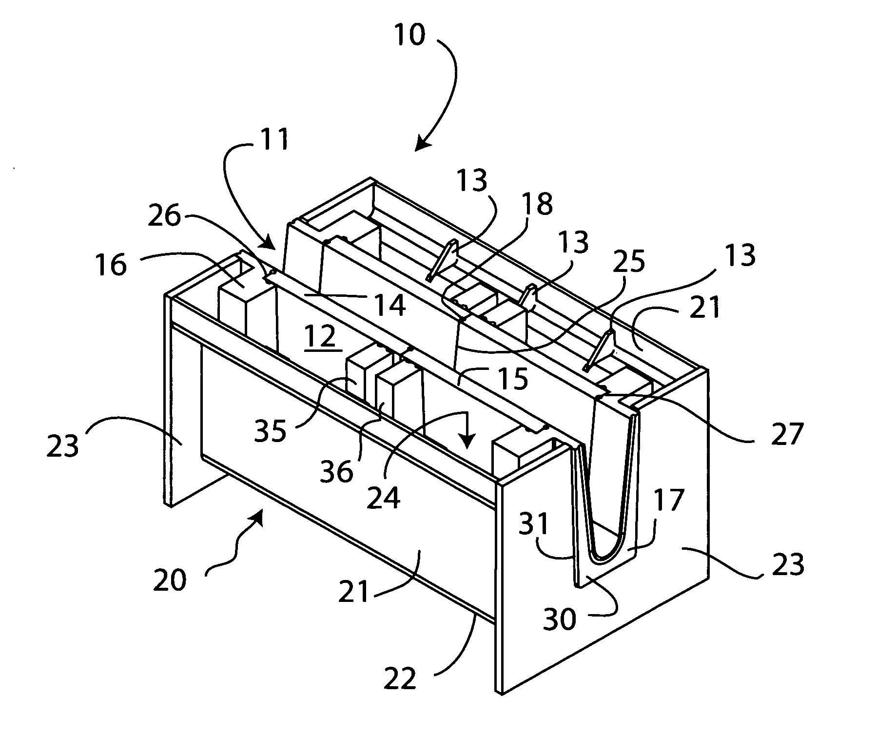
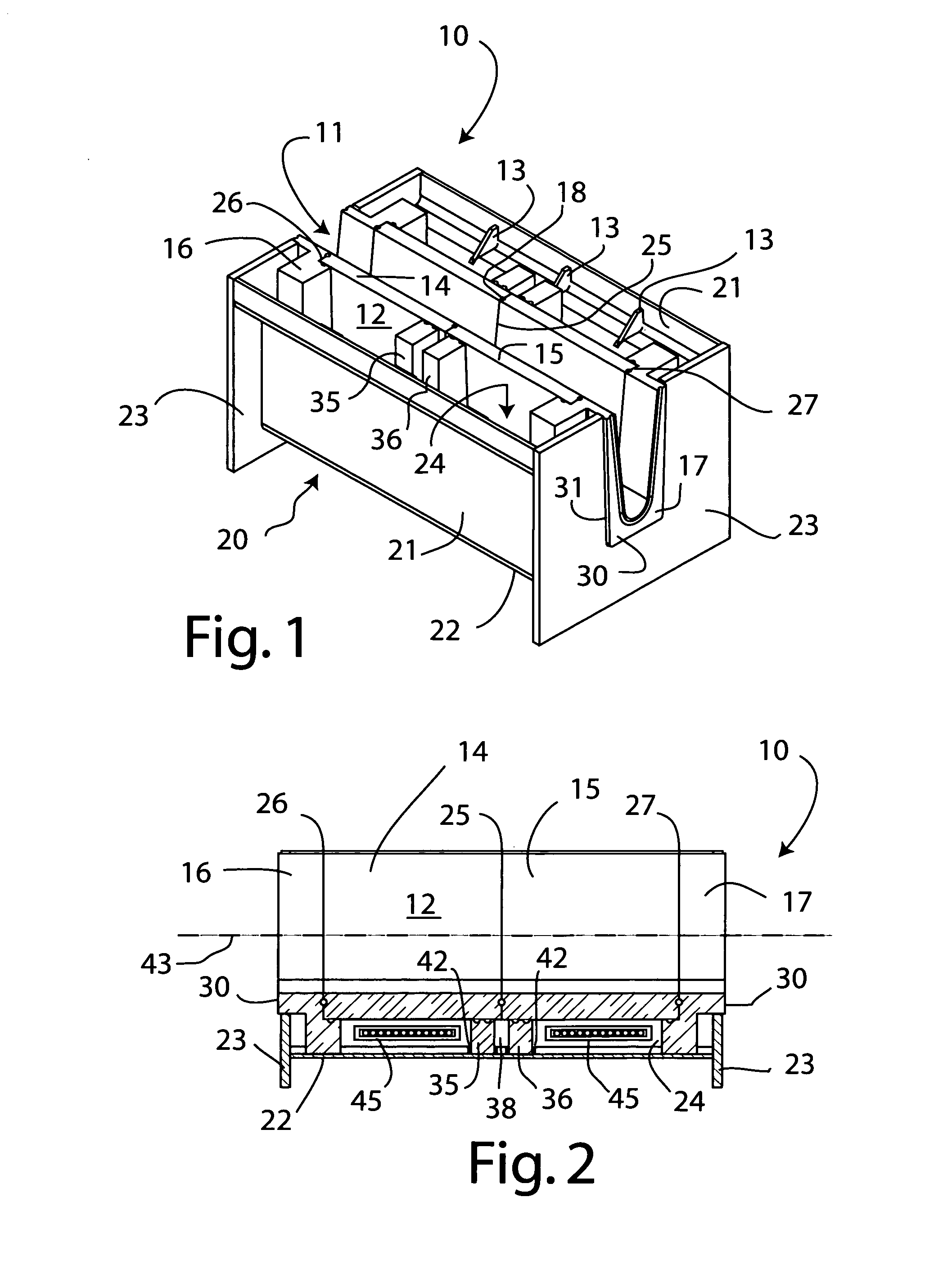
A first exemplary embodiment of the invention, illustrating a metal containment vessel in the form of a trough section of a kind used for conveying molten metal from one location to another, is shown in FIGS. 1 to 3. The trough section 10 may be used alone for spanning short distances, or it may be joined with one or more similar or identical trough sections to form a longer modular metal-conveying trough. It should be noted that the trough section shown in these drawings is normally provided with two horizontal longitudinal metal top plates, one running along each side of metal-conveying channel 11, forming a top part of an external housing 20, but such top plates have been omitted from the drawing to reveal interior elements. Heat insulation, e.g. in the form of refractory insulating boards or fibrous batts, normally provided within the housing, has also been omitted for clarity. Reinforcing elements 13 (provided to strengthen the housing 20) are also shown in FIG. 1 on one side o...


PUM

PropertyMeasurementUnit
distanceaaaaaaaaaa
distanceaaaaaaaaaa
lengthaaaaaaaaaa

Abstract

Exemplary embodiments of the invention relate to a vessel used for containing molten metal, e.g. a trough section for conveying molten metal from one location to another. The vessel has a refractory liner made of at least two refractory liner units positioned end to end, with a joint between the units, the units each having an exterior surface and a metal-contacting interior surface. A housing at least partially surrounds the exterior surfaces of the refractory liner units with a gap present between the exterior surfaces and the housing. Molten metal confinement elements, impenetrable by molten metal, are positioned on opposite sides of the joint within the gap, at least below a horizontal level corresponding to a predetermined maximum working height of molten metal held within the vessel in use, to partition the gap into a molten metal confinement region between the elements and at least one other region that may be used to hold equipment such as electrical heaters that may be damaged by contact with molten metal. Another embodiment employs refractory liner units of different thermal conductivity to maximize heat penetration into the molten metal from heaters in the gap, but to minimize heat loss at the inlet and outlet of the vessel where the end units contact the housing.

Description

BACKGROUND OF THE INVENTIONI. Field of the InventionThis invention relates to vessels used for containing and / or conveying molten metals and, especially, to such vessels having two or more refractory lining units that come into direct contact with each other and with the molten metals during use. More particularly, the invention addresses issues of molten metal leakage and thermal optimization in such vessels.II. Background ArtA variety of vessels for containing and / or conveying molten metals are known. For example, molten metals such as molten aluminum, copper, steel, etc., are frequently conveyed through elongated troughs (sometimes called launders, runners, etc.) from one location to another, e.g. from a metal melting furnace to a casting mold or casting apparatus. In recent times, it has become usual to make such troughs out of modular trough sections that can be used alone or joined together to provide an integral trough of any desirable length. Each trough section usually incl...

Claims


Application Information

Patent Timeline
Patent Type & Authority Applications(United States)
IPC IPC(8): B65D85/00
CPCB22D11/103B22D35/04F27D1/0006B22D35/06F27D3/145F27D1/0003F27D1/0009
Inventor REEVES, ERIC W.BOORMAN, JAMESWAGSTAFF, ROBERT BRUCEWOMACK, RANDAL GUY
Owner NOVELIS INC
Why Eureka
Try Eureka