Micro-fluidic device and sample testing apparatus using the same

a microfluidic device and sample testing technology, applied in the direction of laboratory glassware, instruments, suspensions, etc., can solve the problems of large and expensive automated apparatus used for a related, easy to generate errors when obtaining results of tests, etc., to reduce cross-contamination

Active Publication Date: 2011-10-20
PRECISIONBIOSENSOR INC
View PDF16 Cites 21 Cited by
  • Summary
  • Abstract
  • Description
  • Claims
  • Application Information

AI Technical Summary

Benefits of technology

[0015]Exemplary embodiments provide a microfluidic device with reduced cross-contamination between at least two reaction chambers of the device and a sample testing apparatus including the microfluidic device.

Problems solved by technology

To perform a test according to a predetermined protocol, an experienced tester needs to manually perform a variety of steps such as reagent loading, mixing, separation and movement, reactions, and centrifuges, several times. Therefore, errors may be easily generated when obtaining results of the test.
However, even an experienced clinical pathologist has lots of difficulties in simultaneously performing various tests.
A large and expensive automated apparatus is used for a related art pathological test and a relatively large amount of a test material such as blood is required.
This is referred to as “cross-contamination” and, as a result, reaction results of the reaction chamber may be unreliable, in turn reducing the reliability of the sample testing apparatus.
However, this is problematic in that it increases the overall size of the disc-type microfluidic device.

Method used


Image

  • Micro-fluidic device and sample testing apparatus using the same
  • Micro-fluidic device and sample testing apparatus using the same
  • Micro-fluidic device and sample testing apparatus using the same

Examples


Embodiment Construction

[0054]Reference will now be made in detail to exemplary embodiments, examples of which are illustrated in the accompanying drawings, wherein like reference numerals refer to the like elements throughout. In this regard, the present exemplary embodiments may have different forms and should not be construed as being limited to the descriptions set forth herein. Accordingly, the exemplary embodiments are merely described below, by referring to the figures, to explain aspects of the present description.

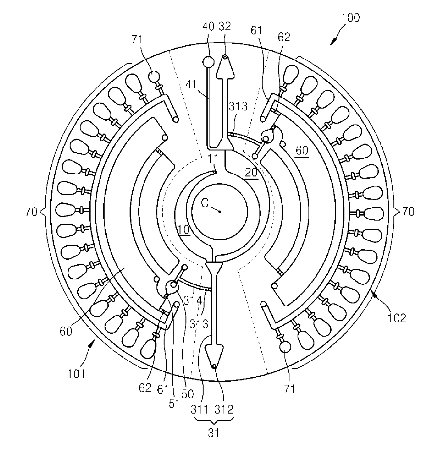
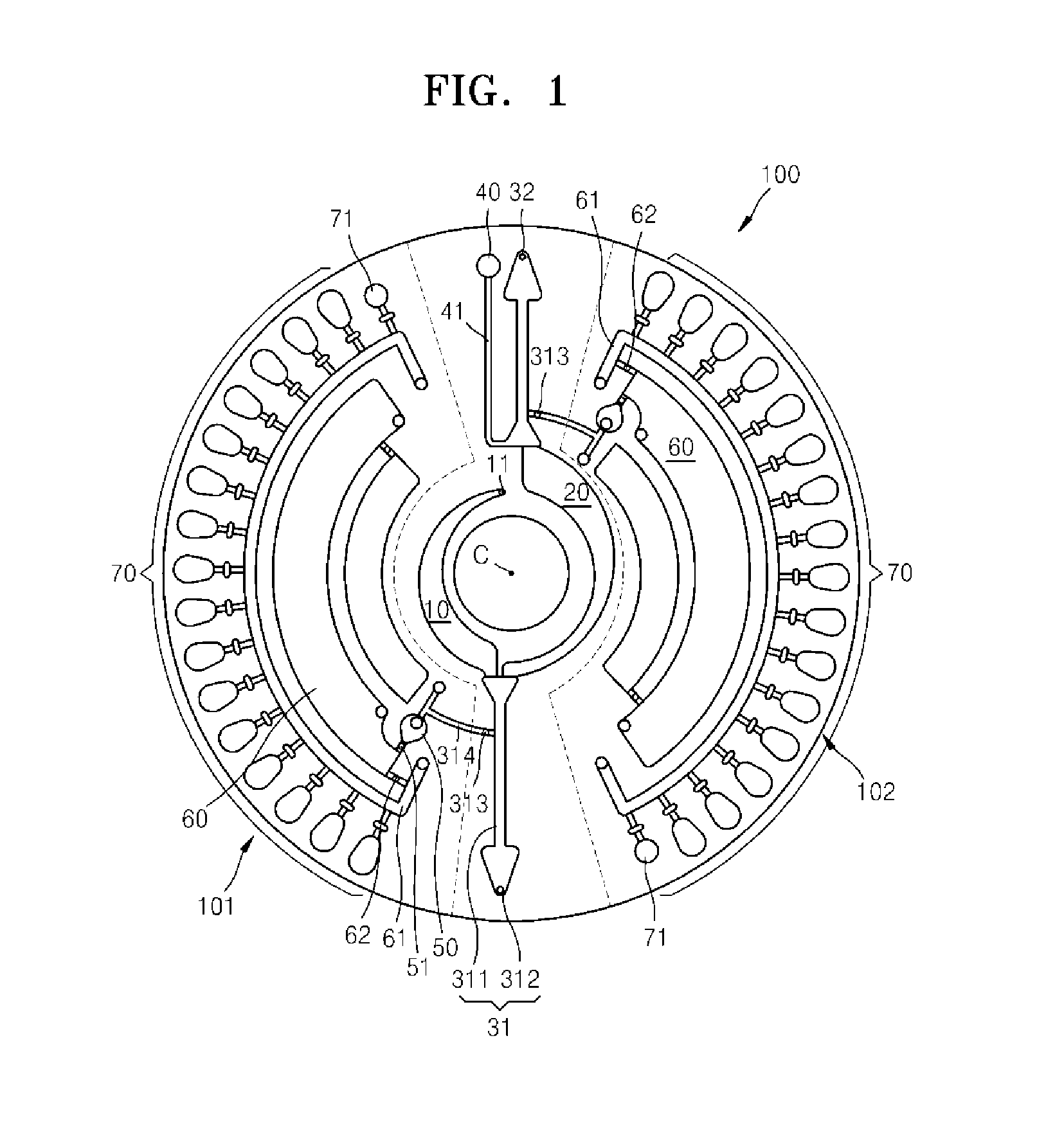
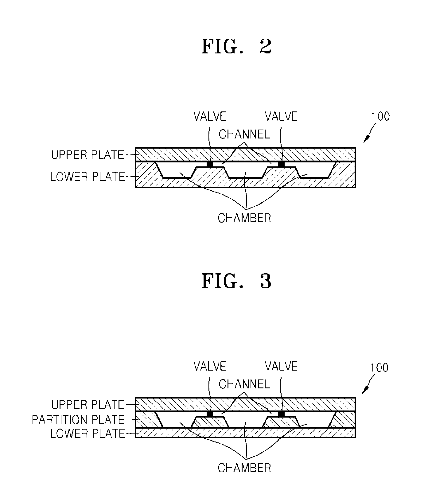
[0055]FIG. 1 is a plan view of a microfluidic device, according to an exemplary embodiment. Referring to FIG. 1, the microfluidic device according to the present exemplary embodiment includes a platform 100 that is rotatable and has the shape of, for example, a disk, and microfluidic structures providing a space for accommodating a fluid and a path for flowing the fluid, in the platform 100. The platform 100 may be rotated around a center of rotation C. That is, in the structures arranged...


PUM

PropertyMeasurementUnit
diameteraaaaaaaaaa
diameteraaaaaaaaaa
diameteraaaaaaaaaa

Abstract

A microfluidic device having a delay structure and a sample testing apparatus including the microfluidic device are provided. The microfluidic device includes: a reaction chamber which contains a reagent capable of reacting with a sample; a distribution channel through which the sample is provided to the reaction chamber; an inlet channel through which the at least one reaction chamber is connected with the distribution channel; and a delay structure which is located between the at least one reaction chamber and the distribution channel, and delays movement of contents of the reaction chamber to the distribution channel.

Description

CROSS-REFERENCE TO RELATED APPLICATIONS[0001]This application is a Continuation-in-Part of U.S. application Ser. No. 12 / 544,636, filed Aug. 20, 2009, which claims priority from Korean Patent Application No. 10-2008-0093372, filed on Sep. 23, 2008 in the Korean Intellectual Property Office, the disclosures of which are incorporated herein by reference in their entirety. This application also claims priority from Korean Patent Application No. 10-2010-086520, filed Sep. 3, 2010 in the Korean Intellectual Property Office, the disclosure of which is incorporated herein by reference in its entirety.BACKGROUND[0002]1. Field[0003]Apparatuses and methods consistent with embodiments relate generally to a microfluidic device and a sample testing apparatus using the same and, more particularly, to a microfluidic device having multiple reaction chambers to contain a sample in order to reduce cross-contamination between the chambers, and a sample testing apparatus including the same.[0004]2. Desc...

Claims


Application Information

Patent Timeline
Patent Type & Authority Applications(United States)
IPC IPC(8): G01N21/00
CPCB01L3/50273B01L3/502753B01L2200/0605B01L2200/0621B01L2400/0677B01L2300/0806B01L2300/0864B01L2300/087B01L2400/0409B01L2200/10B01L3/5027B01L2200/16B01L2300/0861G01N2035/0449G01N33/54386
Inventor KIM, DO GYOONKIM, HAN SANGLEE, YANG UICHO, YOON KYOUNGKIM, NA HUIPARK, SANG BUM
Owner PRECISIONBIOSENSOR INC
Why Eureka
Try Eureka