Method and apparatus for performing retro peritoneal dissection

a retroperitoneal and peritoneal technology, applied in the field of human surgical procedures performed percutaneously, can solve the problems of unwieldy devices, difficult procedures, and high equipment costs, and achieve the effects of avoiding undesired reinsertion procedures, reducing circumference, and saving tim

Inactive Publication Date: 2011-10-20
KLEINER JEFFREY B
View PDF86 Cites 170 Cited by
  • Summary
  • Abstract
  • Description
  • Claims
  • Application Information

AI Technical Summary

Benefits of technology

[0024]In particular embodiments, the ability to adjust the geometric parameters of the cannula end may be achieved by manipulation of the other end of the instrument. For example, providing a turnable component at the opposite end of the instrument, the shape of the other end of the instrument (i.e. the end inserted into the patient) can be adjusted to either expand circumference, reduce circumference, render the opening more or less oblong, etc. In such a manner, it is possible to avoid having to remove the instrument or cannula from the patient's site to adjust the morphology of the instrument, thus saving time, avoiding undesired reinsertion procedures, etc.
[0025]According to another embodiment of the present disclosure, a system is provided wherein the cannula further include one or more electrical probes at the exit portal, which are adapted to assist the surgeon in identifying the presence and location of nerves as the probe is advanced during minimally-invasive surgery, thereby providing further assistance and feedback for guiding the path of the cannula and other surgical instruments to be inserted into the surgical site.
[0026]An expandable tip cannula or dilator may be provided, which functions both as an access portal for surgery and as a system for nerve surveillance, such that the presence and relative position of para-spinal nerves, for example, can be detected as the expandable tip cannula is inserted through the patient's facia and musculature. One particular advantage of determining the position of the lumbosacral plexus with respect to the distal tip of the cannula / dilator is that the lumbosacral plexus can be avoided or gently moved out of the surgeon's way while inserting the cannula / dilator.
[0027]According to one embodiment, the present disclosure provides a system of cannulas adapted to assist the surgeon in guiding the path of surgical instruments received into the intervertebral space, while identifying the presence and location of para-spinal nerves as the cannula is advanced to a patient's intervertebral space during minimally invasive surgery. In various aspects of the present disclosure, probes of the type described in greater detail herein may be comprised of one or more electrodes powered at a low level to sense the position of a para-spinal nerve through continuous real time electromyographic monitoring. Alternatively, these electrodes can be powered at a higher level such that they operate to cauterize blood vessels. Safety systems ensure that power levels sufficient to cause cauterization are not activated if a nerve is sensed to be near the electrodes at the distal end of the cannula.
[0028]According to yet another embodiment of the present disclosure, a system is provided where the cannula or dilator further include one or more electrical probes at the exit portal / patient contacting end, which are adapted to assist the surgeon in identifying the presence and location of nerves as the probe is advanced during minimally-invasive surgery, thereby providing a device for guiding the path of other surgical instruments to be inserted into the intervertebral space.
[0029]According to one embodiment, the present disclosure provides a system of cannulas adapted to assist the surgeon in guiding the path of surgical instruments received into an intervertebral space, while identifying the presence and location of para-spinal nerves as the cannula is advanced to a patient's intervertebral space during minimally invasive surgery. In various aspects of the present disclosure, the system of cannulas may further comprise of one or more electrodes powered at a low level to sense the position of the nerves of the lumbo-sacral plexus through continuous real time electromyographic monitoring. Alternatively, these electrodes can be powered at a higher level such that they operate to cauterize blood vessels. Safety systems ensure that power levels sufficient to cause cauterization are not activated if a nerve is sensed to be near the electrodes at the distal end of the cannula.

Problems solved by technology

These procedures are often difficult due to the location of the spine and adjacent nerves, sensitive anatomy, etc.
This particular piece of equipment is extremely expensive (most quality brands are in the $250,000 range).
The microscope is an unwieldy device requiring uncomfortable gyrations of the surgeon's back and neck in order to gain the necessary view and is a nuisance to drape (a large, sterile plastic bag has to be placed over the eight foot tall structure).
The illumination is also difficult to direct due to the size of the microscope.
A significant danger of performing intervertebral operations or accessing an intervertebral space during spine surgery is that of inadvertently contacting or damaging the para-spinal nerves, including the exiting nerve roots, traversing nerves and the nerves of the cauda equina.
Moreover, intervertebral spaces in the spine have other sensitive nerves disposed at locations which are not entirely predictable prior to insertion of the surgical tool into the intervertebral area.
Accordingly, the danger of pinching or damaging spinal nerves when accessing an intervertebral space has proven to be quite limiting to the methods and devices used during minimally invasive spinal surgery.
In addition, as cannula are received through the patient's back, such as when performing minimally invasive spinal surgery, minor blood vessels are ruptured, thereby blocking the surgeon's vision inside the intervertebral region after the cannula has been inserted.
Other anatomical features at a particular patient may also destruct the surgeon's view or make it difficult to provide illumination within the cannula.
However, these systems and methods have problems and shortcomings, including, but not limited to, limited visualization and lighting in the surgical area, increased risk of impinging upon the nerves of the lumbosacral plexus, and the ilioinguinal and genitofemoral nerves and the risk of devices and / or instruments becoming dislodged during the various procedures, among others.
These problems, alone or in combination, may result in post-operative pain and discomfort experienced by patients of lateral based spinal surgery.
In some instances, these problems require or otherwise lead to additional surgeries, further complicating the likelihood of recovery and successful fusion.
Many retractors fail to provide independent illumination sources or allow the surgeon to visualize the path of access to the surgical site.
Other problems experienced in minimally invasive surgical procedures include the risk of injury caused during the initial probing and dissecting of tissue between the incision and the surgical site.
During this probing, there is increased risk to injury to the lumbar plexus, particularly when the surgeon is attempting to access the lumbar spine.
In addition, there is also an increased risk to the patient's anatomy, and to undesired dissection of various anatomical features between the incision and the surgical site.
This risk of injury typically increases as the probe is inserted deeper into the body of a patient, and continues after the probe has been fully inserted and continuing through dilation, such as by inserting one or more progressive surgical cannula around the dilator proceeds.
Damage to the peritoneal membrane, colon perforation, ureteral or great vessel injury can be the result of the “blind” dissection and is major reason why the lateral, transpoas approach is not a more commonly performed surgical procedure.

Method used


Image

  • Method and apparatus for performing retro peritoneal dissection
  • Method and apparatus for performing retro peritoneal dissection
  • Method and apparatus for performing retro peritoneal dissection

Examples


Embodiment Construction

[0056]Various embodiments of the apparatus and methods of the present disclosure are described in detail below. The following patents are hereby incorporated by reference for the express purpose of describing the technology related to the use of illumination and video capabilities described herein, including the use of camera chips and CCD or CMOS technology: U.S. Pat. No. 6,310,642; U.S. Pat. No. 6,275,255; U.S. Pat. No. 6,043,839; U.S. Pat. No. 5,929,901; U.S. Pat. No. 6,211,904; U.S. Pat. No. 5,986,693; and U.S. Pat. No. 7,030,904.

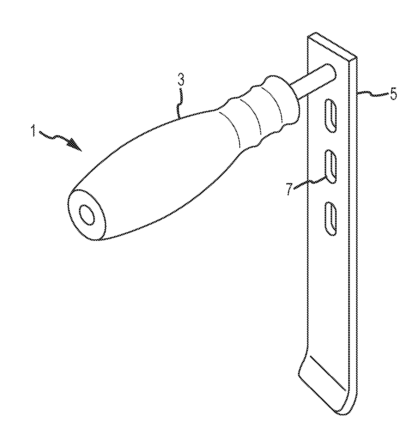
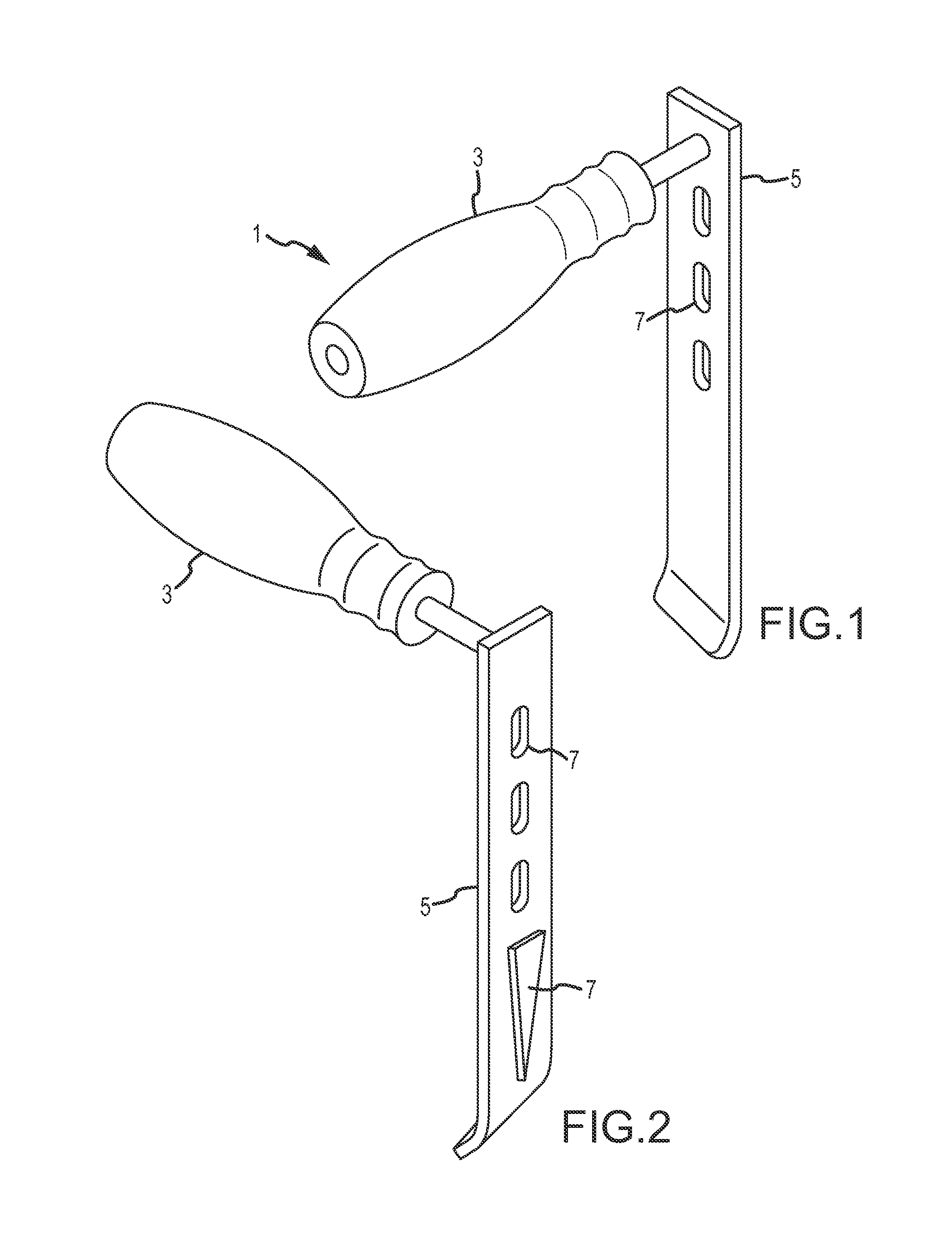
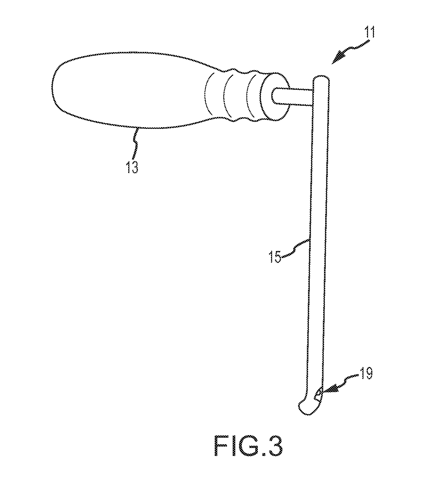
[0057]Referring now to FIGS. 1-4, a modified retractor according to embodiments of the present disclosure is shown, which incorporates illumination and / or video capabilities of the nature described herein. This “Sherrill” retractor comprises a longitudinal blade, which extends longitudinally a length sufficient for inserting into a patient to assist in retracting tissue between the incision and the surgical site, and may incorporate one more lumens inte...


PUM


Abstract

The foregoing application describes a system and method of performing a minimally invasive surgical operation. More specifically, the invention involves the use of disposable cannula and slender dilators of variable lengths, which incorporate a source of illumination to carry light to a surgical site and video capabilities for capturing and displaying images from a CMOS or CCD camera device. According to one embodiment, fiber optics run semi-circumferentially or along walls of the cannula/dilator and terminate at about a centimeter from the distal end of the cannula/dilator, thereby preventing illumination from “bottoming out” at the floor of the incision. According to one alternate embodiment, the light fibers may be fashioned in an annulus around one or more camera chips to provide illumination and video of the surgical site. In still another embodiment, the light fibers may be replaced by light emitting diodes in a more remote light source or alternatively at the distal-tip of the CMOS or CCD camera device.

Description

CROSS-REFERENCE TO RELATED APPLICATIONS[0001]This application claims the benefit of U.S. Provisional Patent Application Ser. No. 61 / 326,138, filed Apr. 20, 2010, and U.S. Provisional Patent Application Ser. No. 61 / 355,250 filed Jun. 16, 2010, the entire disclosures of which are hereby incorporated herein by reference.FIELD OF THE INVENTION[0002]This disclosure relates to human surgical procedures performed percutaneously, and more specifically to a novel retractor, neuro-monitoring probe and progressive cannula system that enhances illumination and visibility. The disclosure also relates to a system and method for providing one or more disposable or reusable camera / video devices, including camera / video devices incorporating CCD and / or CMOS technology.BACKGROUND OF THE INVENTION[0003]Surgical procedures to address illness, disease or injury vary depending on a number of factors, including the ability of the surgeon(s) to access and perform the necessary procedures at the affected sit...

Claims


Application Information

Patent Timeline
Patent Type & Authority Applications(United States)
IPC IPC(8): A61B1/00
CPCA61B1/05A61B1/0607A61B1/0676A61B1/0684A61B5/4893A61B17/0218A61B2019/521A61B19/5212A61B2017/00022A61B2017/00991A61B2017/0256A61B2017/0262A61B2019/5206A61B17/3421A61B90/361A61B2090/306A61B2090/309
Inventor KLEINER, JEFFREYADAIR, JEFFREYWIGGINS, KEVIN
Owner KLEINER JEFFREY B
Why Eureka
Try Eureka