[0009]Whereas in prior art
ratchet systems a pawl binds against the teeth of a ratchet mechanism to prevent backward motion and requires relief from any load placed upon the teeth prior to pivoting the pawl out of the way to disengage the ratchet mechanism, positioning the ratchet pawl on a moveable ratchet engagement member capable of shifting the entire pawl away from the ratchet teeth advantageously provides the ratchet mechanism with the ability to engage and disengage even when under a
heavy load.
[0012]In one aspect of the invention, the
reducer instrument may have a clamp member for selectively securing the
coupling device to the instrument, a
reducer member for shifting the elongate member into place within the coupling device, and optionally a locking member inserter to secure a locking member to the coupling device in order to capture the elongate member therein. One or more of the members, or a separate drive
actuator member, may be provided with a
helical recess on its inner or outer surface to interact with a rolling element coupled to another member in order to transfer rotational motion of one portion of the instrument into
linear motion of the same portion or another portion of the instrument. In this manner, the instrument responds to manipulation in much the same manner as a threaded drive system, although friction is greatly reduced due to the presence of rolling elements instead of complementary threads. The need for
lubrication is thereby minimized or eliminated, and
cleanability of the instrument is improved since the drive system can be fully sealed.
[0014]The components of the reducer instrument may be generally cylindrical in shape to minimize the profile of the apparatus, reducing the size of the incision necessary for
surgery and subsequently reducing the
recovery time of the patient. In alternative embodiments, the components can have other configurations such as
hexagonal prism or rectangular
prism configurations.
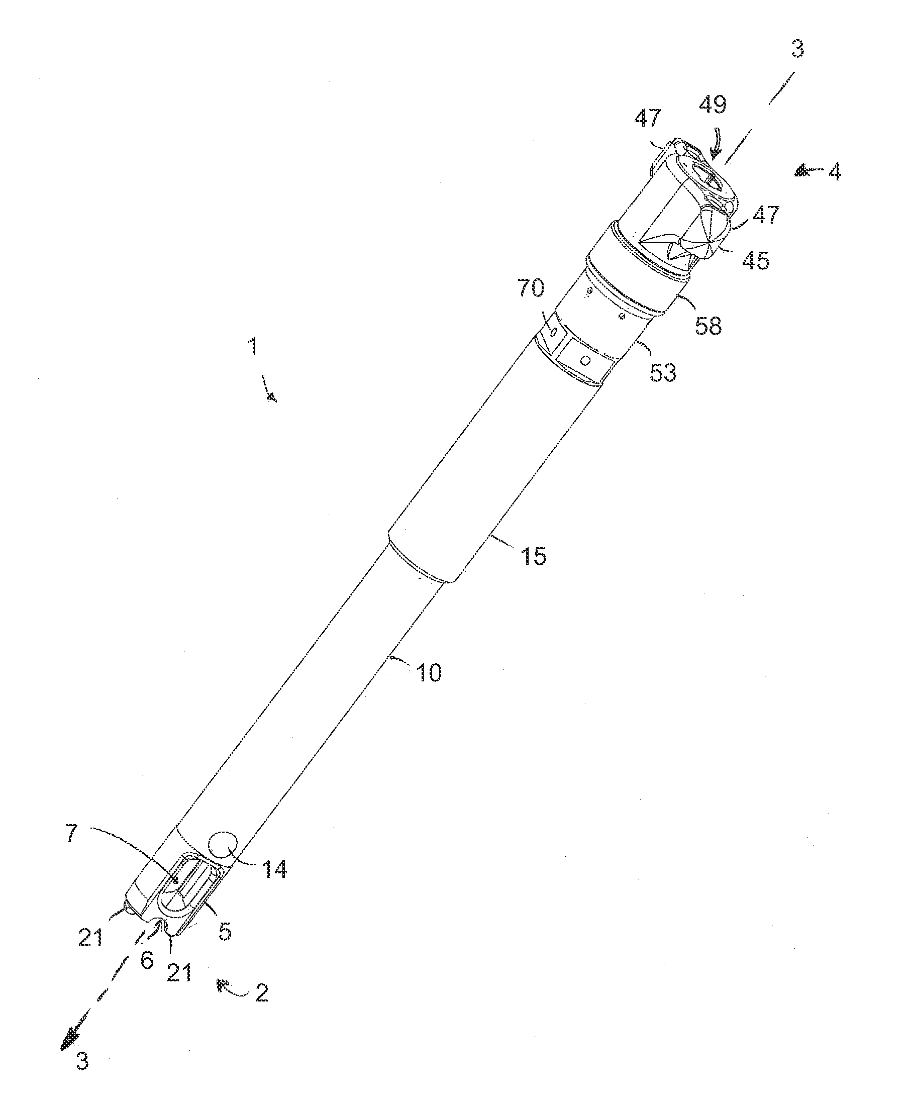
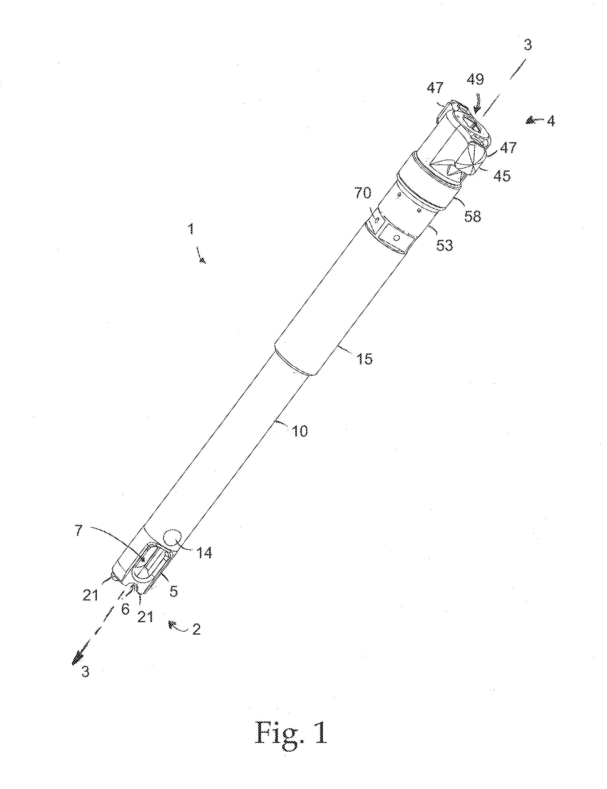
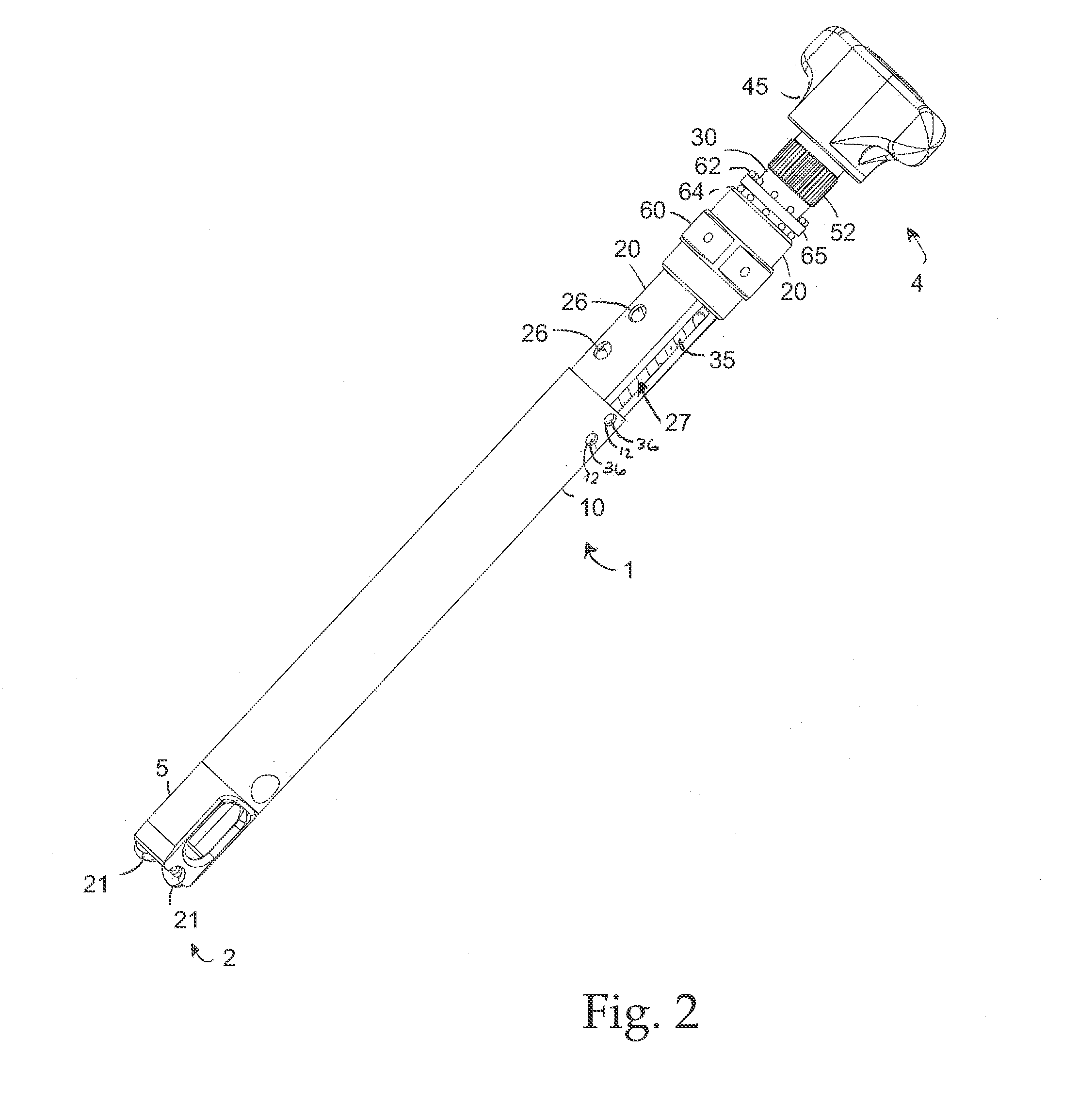
[0017]In one preferred form, the reducer instrument includes an elongate stationary clamp member; a rotatable drive
actuator operatively coupled to the clamp member; a reducing member operatively coupled to the clamp member and drive
actuator so that it is shiftable along the axis of the elongate clamp member; and optionally a cap inserter. In a preferred form, the reducing member includes a sleeve portion surrounding the clamp member, while the drive member is positioned within an axial bore of the clamp member, and has a helical recess about its outer surface. The helical recess of the drive member is sized and configured to receive rolling elements that extend through elongate openings of the clamp member and are linked to the reducing member disposed about the outer surface of the clamp member. Elongate openings in the clamp member may be positioned so as to allow the rolling elements to contact both the helical recess of the drive member and the interior surface of the reducing member even though the clamp member is disposed between the two. In this form, rotation of the drive member guides the rolling elements along the helical recess, shifting them through the elongate opening in the clamp member and, due to their linkage to the reducing member, causing the reducing member to shift along the exterior of the clamp member. In another preferred form, a ratchet
assembly is provided in order to allow rotation of the drive member in one direction but prevent rotation of the drive member in the opposite direction unless the ratchet
assembly is disengaged.
[0018]The instruments described herein may be adapted for use with particular coupling devices, such as those described in U.S. Pat. No. 7,141,051 (issued on Nov. 28, 2006), U.S.
Patent Application 2008 / 0045955 (Ser. No. 11 / 839,843), or U.S.
Patent Application 2007 / 0225711 (Ser. No. 11 / 726,868), all of which applications are hereby fully incorporated by reference as if fully set forth herein. The instrument, anchor member, and coupling device may all be fully cannulated so that a wire can be passed therethrough for minimally invasive surgical (MIS) systems. In such systems, a guide wire is attached to a predetermined point on the surface of a bone, and then elements of an
implant such as the coupling device mentioned above are passed around the guide wire so that the guide wire directs the
implant elements to the predetermined point on the bone. Similarly, the instrument for reducing an elongate member into the coupling device also can be cannulated, i.e. contain a pathway through the center of the tool so that the aforementioned guide wire threaded through the anchor and coupling device can be threaded through the body of the instrument and is able to direct implantation or manipulation of the system without interfering with the operation of the tool. The accuracy gained by use of such a guide wire reduces the amount of tissue affected by the surgical procedure and reduces
recovery time for the patient.

