
Photovoltaic module frame

a photovoltaic module and accessory technology, applied in the direction of heat collector mounting/support, light and heating apparatus, pv power plants, etc., can solve the problems of frame damage, lower productivity, efficiency and stability, and frame member twisting and damage to the photovoltaic module, so as to prevent the frame member from twisting and damaging the photovoltaic module, simple injection method, and the effect of reducing operation tim

Inactive Publication Date: 2011-10-27
DAEJU SYST
View PDF9 Cites 25 Cited by
  • Summary
  • Abstract
  • Description
  • Claims
  • Application Information

AI Technical Summary

Benefits of technology

[0010]The purpose of the present invention is to prevent any damage of the photovoltaic module by allowing the frame member to accurately and solidly connect to prevent any twisting of the frame member.
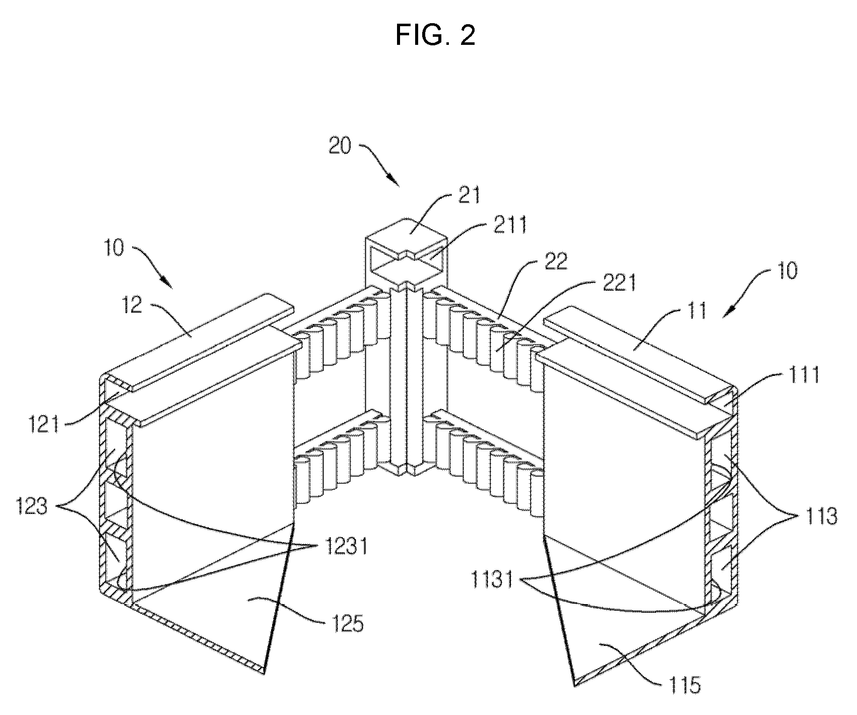
[0030]The present invention, photovoltaic module frame, has the corner member that includes the body unit, which forms part of the horizontal member and vertical member, to provide quality assurance by standardizing the photovoltaic module frame by promoting an accurate coupling between the frame member and other frame members from the mentioned corner member and furthermore, resolve the cracking issue in between the connected frame members.

Problems solved by technology

By simply inserting into the corner key, this method causes safety issues due to the sharpness of the module cornering, which needs further actions operated by the installer.
Also, the actions operated to solve the sharpness issue may cause damage onto the frame and lower productivity, efficiency and stability.
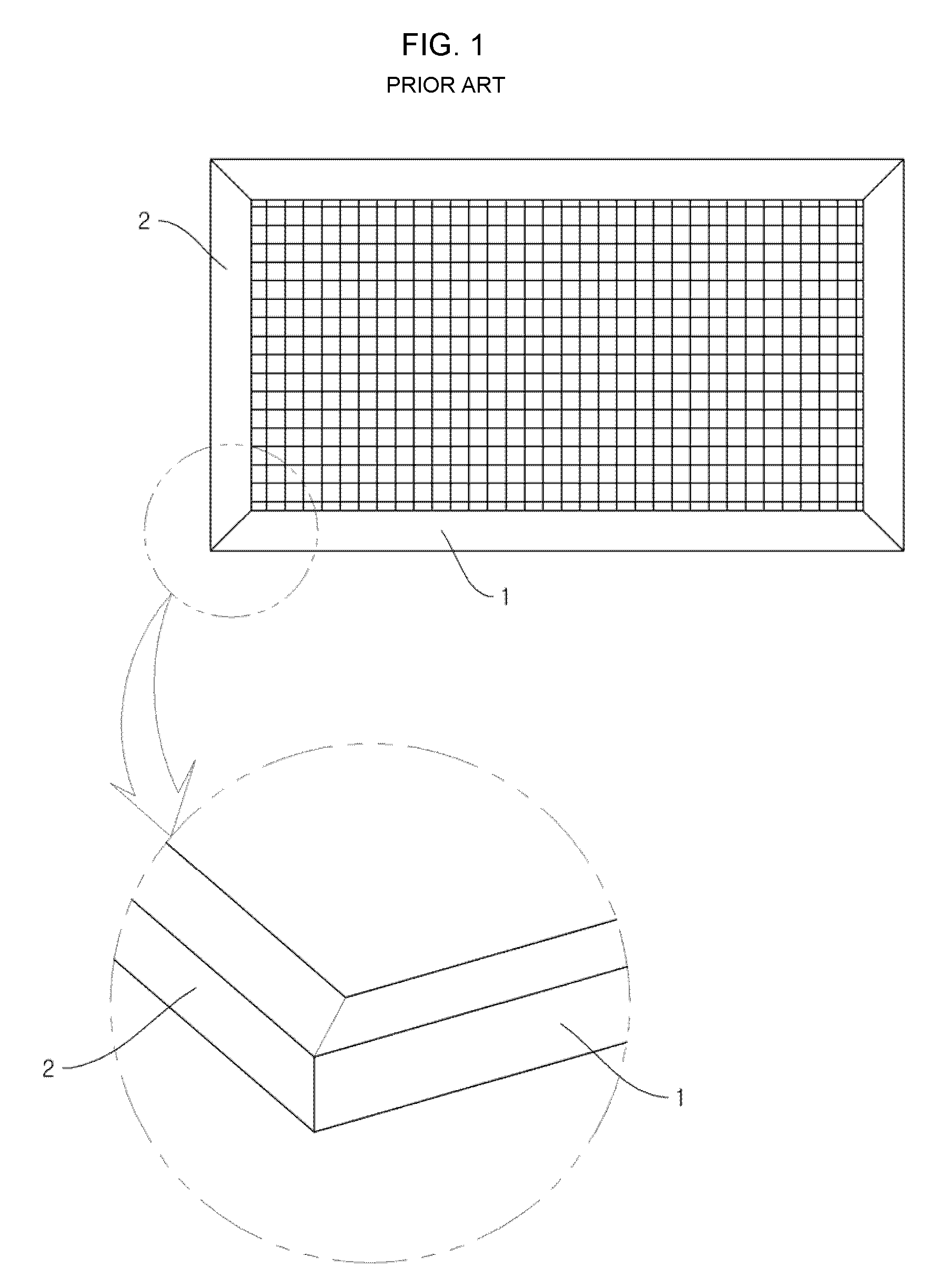
Furthermore, traditional photovoltaic module frames have the horizontal member and vertical member to couple directly, which may lower solidity and accuracy in coupling so that the exterior is faulty, and the frame can be twisted from strong wind and other disturbance, which may cause damage to the photovoltaic module that, is inserted into the frame.

Method used


Image

  • Photovoltaic module frame
  • Photovoltaic module frame
  • Photovoltaic module frame

Examples


Embodiment Construction

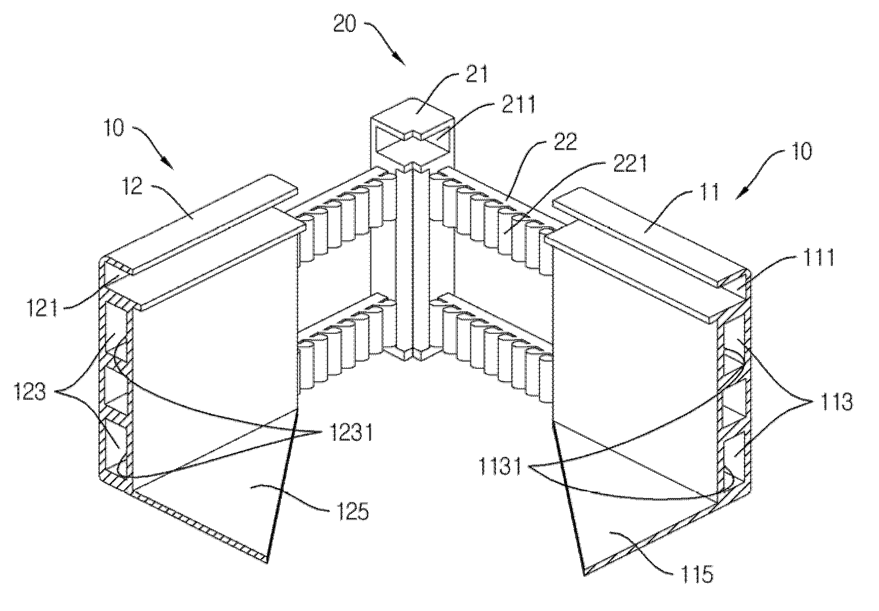
[0038]The present invention relates to an apparatus for a photovoltaic module frame assembly comprising a frame member including a vertical member and horizontal member that cover the outer circumference the photovoltaic module, which transforms solar energy into electric energy, and corner member that performs connections and fixation between the horizontal member and vertical member, which provides a solution to alleviate traditional frame structure issues that relate to the sharpness of the corner so that any accidents that may be caused by the corner can be prevented and enhance safety. Also a groove is included to fix the frame onto the corner member that, which covers the photovoltaic module and does not have any sides, and allows accurate coupling by fitting into the frame member so that various designs and formations can be provided.

[0039]The figures attached illustrate the preferred embodiment of the present invention. All terms that are not defined in particular are to fol...


PUM


Abstract

An apparatus for a photovoltaic module frame assembly comprising a frame member including a vertical member and horizontal member that cover the outer circumference the photovoltaic module, which transforms solar energy into electric energy, and corner member that performs connections and fixation between the horizontal member and vertical member, which provides a solution to alleviate traditional frame structure issues that relate to the sharpness of the corner so that any accidents that may be caused by the corner can be prevented and enhance safety. Also a groove is included to fix the frame onto the corner member that, which covers the photovoltaic module and does not have any sides, and allows accurate coupling by fitting into the frame member so that various designs and formations can be provided.

Description

CROSS REFERENCE[0001]This application claims foreign priority under Paris Convention and 35 U.S.C. §119 to Korean Patent Application No. 10-2010-0038187, filed Apr. 23,2010 with the Korean Intellectual Property Office.BACKGROUND OF THE INVENTION[0002]1. Technical Field[0003]The present invention relates to an apparatus for a photovoltaic module frame assembly comprising a frame member including a vertical member and horizontal member that cover the outer circumference the photovoltaic module, which transforms solar energy into electric energy, and corner member that performs connections and fixation between the horizontal member and vertical member, which provides a solution to alleviate traditional frame structure issues that relate to the sharpness of the corner so that any accidents that may be caused by the corner can be prevented and enhance safety. Also a groove is included to fix the frame onto the corner member that, which covers the photovoltaic module and does not have any...

Claims


Application Information

Patent Timeline
Patent Type & Authority Applications(United States)
IPC IPC(8): H01L31/048
CPCF24J2/5211H02S30/10F24J2/526F24S25/20F24S25/65Y02E10/50H01L31/042
Inventor JANG, BYUNG-RAK
Owner DAEJU SYST
Learn More