Landing gear provided with energy absorber means, an aircraft provided with said landing gear, and a method of landing

a technology of energy absorption and landing gear, which is applied in the direction of transportation and packaging, emergency equipment, floating devices, etc., can solve the problems of aircraft facing vertical speed, landing gear damage, and standard landing gear ineffective on water, and achieve significant energy absorption

Inactive Publication Date: 2011-10-27
EUROCOPTER
View PDF8 Cites 14 Cited by
  • Summary
  • Abstract
  • Description
  • Claims
  • Application Information

AI Technical Summary

Benefits of technology

[0057]It can be understood that by virtue of its volume, the airbag presents resistance to penetration into a flexible material such as water, mud, or even snow. This obtains significant energy absorption in the event of alighting in water, which is impossible with conventional landing gear.

Problems solved by technology

Similarly, it can readily be understood that standard landing gear is ineffective on water since it penetrates into the water without absorbing significant energy.
Unfortunately, in the event of a crash, the aircraft may be confronted with vertical speeds that are faster than the speeds set down by civil certification regulations.
The landing gear can then be damaged, since the landing gear is then subjected to forces for which, by definition, it was not initially designed.
Similarly, those forces greater than the usual forces are applied to the structure of the aircraft via the fastening points of the landing gear and, as a result, can give rise to dangerous damage.
Under such circumstances, standard landing gear does not necessarily comply with military qualification regulations.
As a result it would appear to be difficult to implement that solution on an existing aircraft without giving rise to constraints, or at least to difficulties, and in any event to modifications and to reinforcements.

Method used


Image

  • Landing gear provided with energy absorber means, an aircraft provided with said landing gear, and a method of landing
  • Landing gear provided with energy absorber means, an aircraft provided with said landing gear, and a method of landing
  • Landing gear provided with energy absorber means, an aircraft provided with said landing gear, and a method of landing

Examples


Embodiment Construction

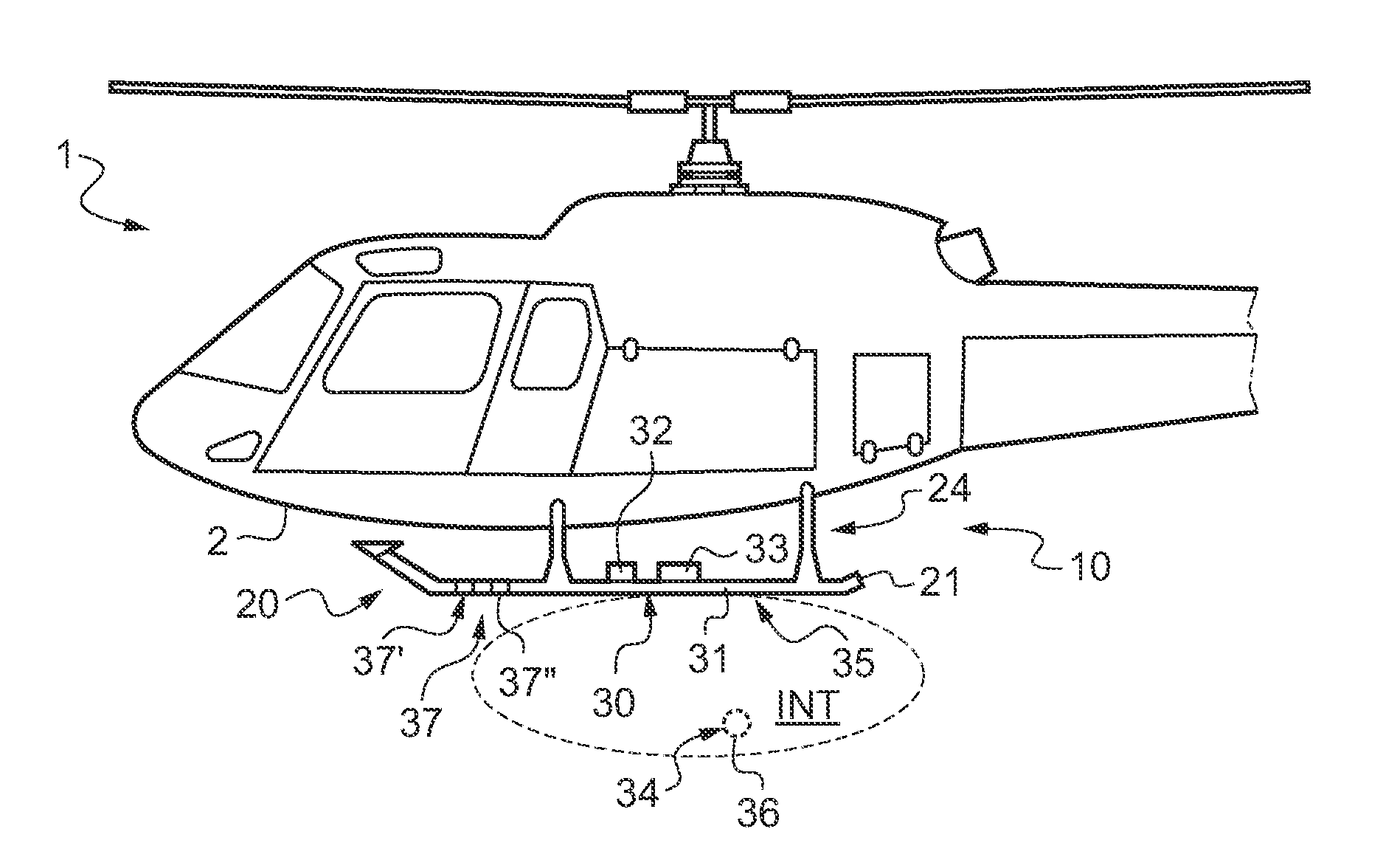
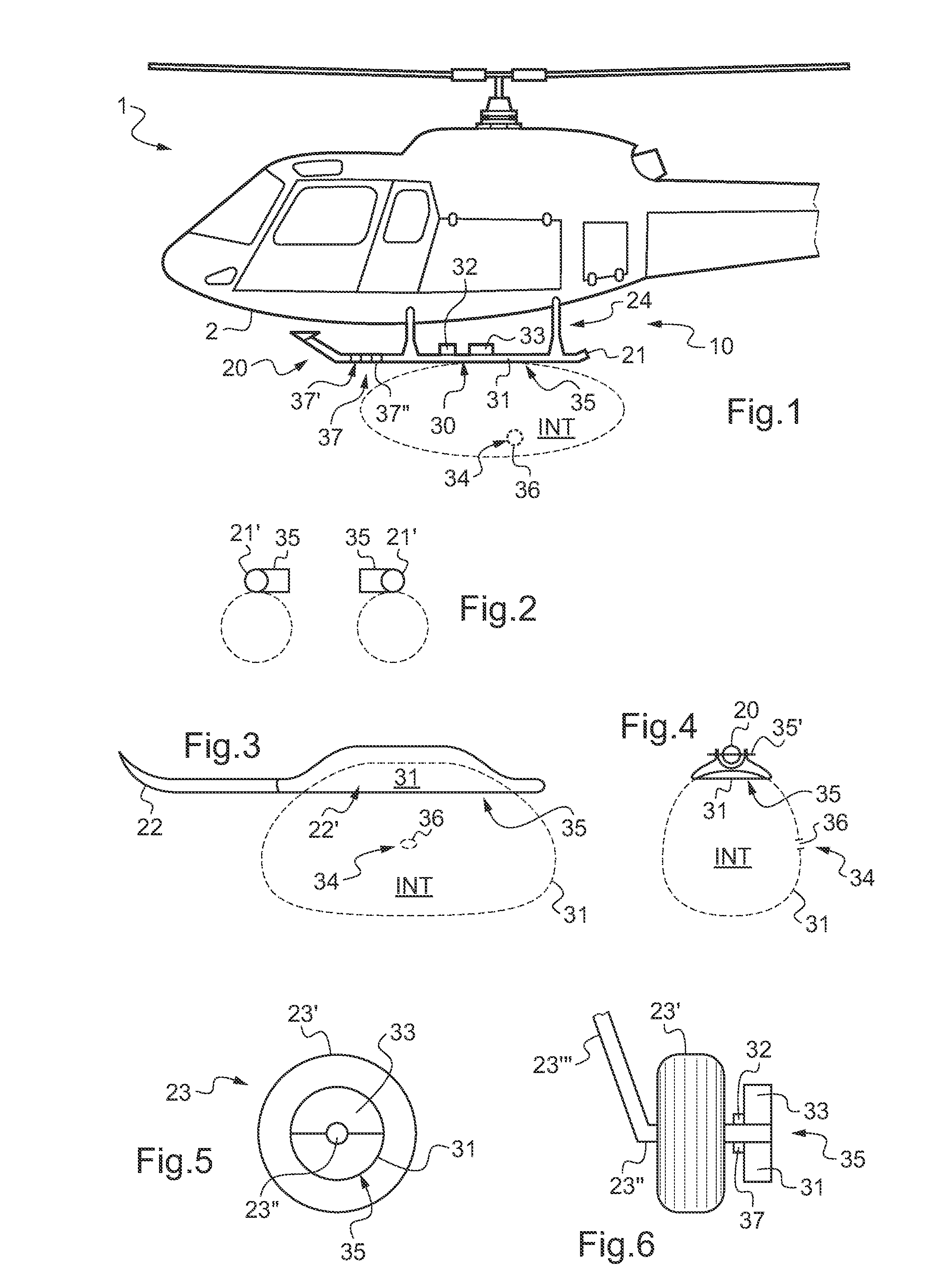
[0067]FIG. 1 shows an aircraft 1 having landing gear 20 of the invention, and more particularly it shows a helicopter type rotorcraft.

[0068]The landing gear 20 shown in FIG. 1 is provided with contact means 20 for making contact with a contact surface, specifically it is provided with two skids 21 connected via two connecting cross-members 24 to the fuselage 2 of the aircraft 1.

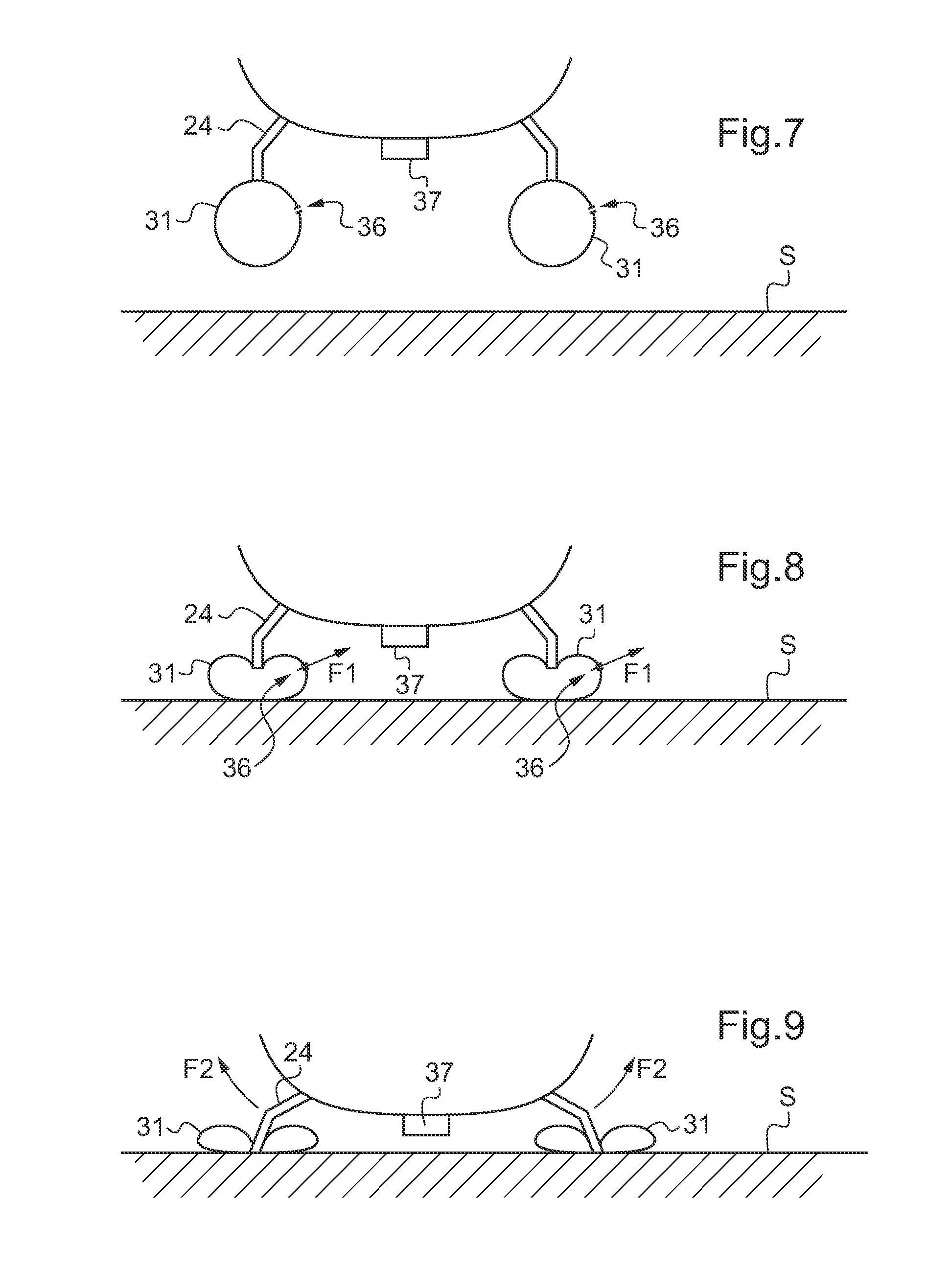
[0069]The landing gear is also fitted with at least one energy absorber means 30 suitable, in the event of a non-standard landing, for absorbing extra energy relative to the assembly comprising the contact means and the means connecting the contact means to the fuselage 2, i.e. the skids 12 and the cross-members 24 in FIG. 1.

[0070]The energy absorber means 30 are provided with at least one inflatable airbag 31 secured to a contact means 20. It should be observed that when the landing gear has a plurality of elongate contact means of the ski or skid 21 type, it is advantageous to provide one inflatable airbag ...


PUM


Abstract

Aircraft landing gear (10) provided with at least one contact means (20) for making contact with a contact surface (S). The landing gear includes energy absorber means (30) provided with an inflatable airbag (31) secured to said contact means (20), said energy absorber means (30) being provided with control means (32) and with at least one inflation means (32) for inflating said airbag (31) under the control of said control means (32), said energy absorber means (30) including adjuster means (34) for adjusting the pressure that exists inside (INT) said airbag (31).

Description

CROSS REFERENCE TO RELATED APPLICATIONS[0001]This application claims the benefit of FR 10 01775 filed on Apr. 26, 2010, the disclosure of which is incorporated in its entirety by reference herein.BACKGROUND OF THE INVENTION[0002](1) Field of the Invention[0003]The present invention relates to landing gear provided with energy absorber means, to an aircraft provided with said landing gear, and to a method of landing.[0004](2) Description of Related Art[0005]Conventionally, an aircraft includes landing gear via which it stands on a contact surface. It should be observed that in the text below, the term “contact surface” is used to mean the contact surface against which the contact means bear on landing. For example, the contact surface may include ground as such, the deck of the ship, the roof of a building, or indeed a liquid surface such as water in particular when alighting at sea.[0006]For example, the landing gear may be provided with three or four wheeled undercarriages that con...

Claims


Application Information

Patent Timeline
Patent Type & Authority Applications(United States)
IPC IPC(8): B64C25/58B64C25/56
CPCB64C25/52B64C27/006B64D2201/00B64D25/00B64C2025/325
Inventor FERRIER, JEAN-JACQUESPRUDHOMME-LACROIX, PIERRE
Owner EUROCOPTER
Why Eureka
Try Eureka