Compensation of distortion from SBS/IIN suppression modulation

a suppression modulation and distortion compensation technology, applied in the field of optical communication, can solve the problems of non-linear transmission effects, intermodulation distortion of transmitted signals, increase in noise and distortion from sbs and/or iin effects, etc., to reduce iin, increase sbs threshold, and broaden laser linewidth

Active Publication Date: 2011-10-27
ARRIS SOLUTIONS
View PDF24 Cites 4 Cited by
  • Summary
  • Abstract
  • Description
  • Claims
  • Application Information

AI Technical Summary

Benefits of technology

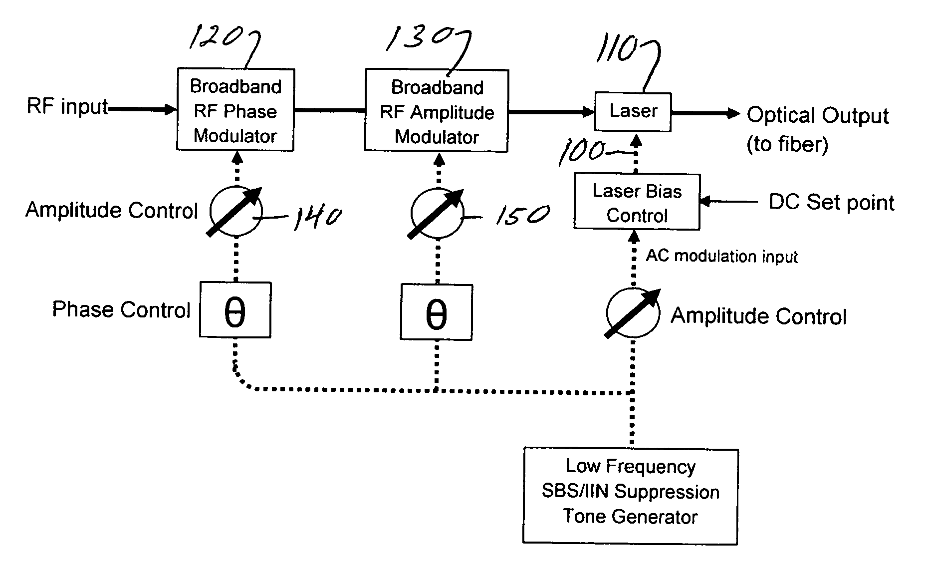
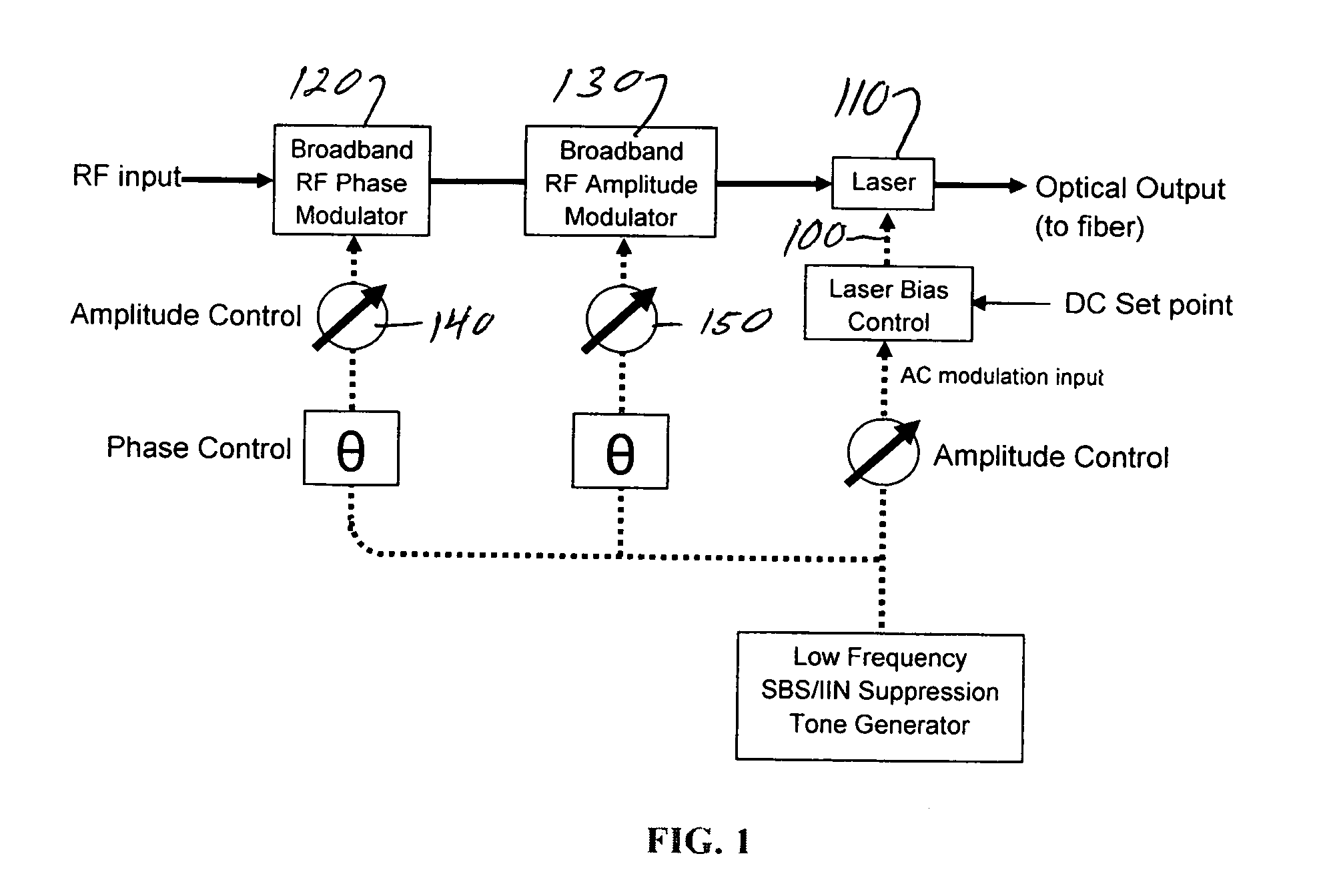
[0010]According to an embodiment of the invention, a process comprises: modulating a laser that is coupled to a fiber; modulating the laser with a member selected from the group consisting of low frequency thermal modulation or bias modulation to broaden a laser linewidth, increase an SBS threshold and reduce an IIN; and modulating the laser with a predistorting modulation selected from the group consisting of phase modulation or amplitude modulation, the predistorting modulation being of equal magnitude but opposite phase as that produced in at least one member selected from the group consisting of the laser or the fiber as a result of the low frequency thermal modulation or bias modulation. Accordi

Problems solved by technology

This can lead to non-linear transmission effects if fiber dispersion is not zero.
However, the non-zero dispersion interacts with laser chirp to produce intermodulation distortion of the transmitted

Method used


Image

  • Compensation of distortion from SBS/IIN suppression modulation
  • Compensation of distortion from SBS/IIN suppression modulation
  • Compensation of distortion from SBS/IIN suppression modulation

Examples


Embodiment Construction

[0016]Embodiments of the invention and the various features and advantageous details thereof are explained more fully with reference to the nonlimiting embodiments that are illustrated in the accompanying drawings and detailed in the following description. Descriptions of well known starting materials, processing techniques, components and equipment are omitted so as not to unnecessarily obscure the embodiments of the invention in detail. It should be understood, however, that the detailed description and the specific examples, while indicating preferred embodiments of the invention, are given by way of illustration only and not by way of limitation. Various substitutions, modifications, additions and / or rearrangements within the spirit and / or scope of the underlying inventive concept will become apparent to those skilled in the art from this disclosure.

[0017]Within this application one or more publications is(are) referenced by Arabic numeral(s), within parentheses or brackets. The...


PUM


Abstract

A method includes modulating a laser that is coupled to a fiber; modulating the laser with a member selected from the group consisting of low frequency thermal modulation or bias modulation to broaden a laser linewidth, increase an SBS threshold and reduce an IIN; and modulating the laser with a predistorting modulation selected from the group consisting of phase modulation or amplitude modulation, the predistorting modulation being of equal magnitude but opposite phase as that produced in at least one member selected from the group consisting of the laser or the fiber as a result of the low frequency thermal modulation or bias modulation. An apparatus includes a laser; and a fiber coupled to the laser, wherein the laser is i) modulated ii) modulated with a member selected from the group consisting of low frequency thermal modulation or bias modulation to broaden a laser linewidth, increase an SBS threshold and reduce an IIN and iii) modulated with a predistorting modulation selected from the group consisting of phase modulation or amplitude modulation, the predistorting modulation being of equal magnitude but opposite phase as that produced in at least one member selected from the group consisting of the laser or the fiber as a result of the low frequency thermal modulation or bias modulation.

Description

CROSS-REFERENCES TO RELATED APPLICATIONS[0001]This application claims a benefit of priority under 35 U.S.C. 119(e) from copending provisional patent applications U.S. Ser. No. 61 / 342,896, filed Apr. 21, 2010 and U.S. Ser. No. 61 / 342,897, filed Apr. 21, 2010 the entire contents of both of which are hereby expressly incorporated herein by reference for all purposes.BACKGROUND INFORMATION[0002]1. Field of the Invention[0003]Embodiments of the invention relate generally to the field of optical communications. More particularly, an embodiment of the invention relates to compensation of distortion from SBS / IIN suppression modulation.[0004]2. Discussion of the Related Art[0005]Directly modulated lasers are commonly used in hybrid fiber-coax systems to transmit RF signals over long distances using optical fibers. These lasers are usually single mode and operate at wavelengths near 1310 nm or 1550 nm. The advantage of 1310 nm is most installed fiber has zero dispersion around this wavelength...

Claims


Application Information

Patent Timeline
IPC IPC(8): H04B10/12
CPCH01S5/0427H01S5/06213H04B10/2537H01S5/06246H01S2301/03H01S5/0622
Inventor ISHAUG, BRIAN
Owner ARRIS SOLUTIONS
Why Eureka
Try Eureka