Centrifugal micro-fluidic device and method for detecting analytes from liquid specimen

a microfluidic device and liquid specimen technology, applied in the field of centrifugal microfluidic devices and methods for detecting analytes from liquid specimens, can solve the problems of large amount of labeling reagents, insufficient combination, and rarely satisfied practical requirements, so as to enhance reaction efficiency and improve sensitivity

Inactive Publication Date: 2011-10-27
SAMSUNG ELECTRONICS CO LTD
View PDF4 Cites 27 Cited by
  • Summary
  • Abstract
  • Description
  • Claims
  • Application Information

AI Technical Summary

Benefits of technology

One or more exemplary embodiments provide a centrifugal micro-fluidic device for detection of analytes from a liquid specimen with improved sensitivity wherein a repeated flow of the liquid specimen induced by a combination of capillary force and centrifugal force enhances reaction efficiency, as well as a method for detection of analytes from a liquid specimen using the micro-fluidic device.

Problems solved by technology

However, since the analyte is primarily combined with the labeling reagent, a large amount of labeling reagent is required, although this requirement is seldom satisfied in view of practical aspects.
Furthermore, combination of the analyte and each reagent is terminated within only a single fluid sample stream in one direction, thus resulting in insufficient combination and causing decrease in sensitivity and difficulties in quantitative analysis.
The kit does not have an active device for controlling a re-lysis rate of the detectable signal generator and, therefore, the detectable signal generator is excessively re-lysed by a constant volume of a fluid sample flowing thereto, thus causing waste of the detectable signal generator at an early stage.
On the other hand, re-lysis of the detectable signal generator is drastically reduced in a later stage, thus entailing difficulties in sensitive detection of the analyte.

Method used


Image

  • Centrifugal micro-fluidic device and method for detecting analytes from liquid specimen
  • Centrifugal micro-fluidic device and method for detecting analytes from liquid specimen
  • Centrifugal micro-fluidic device and method for detecting analytes from liquid specimen

Examples


Embodiment Construction

Hereinafter, and practical methods thereof will be exemplary embodiments will be described with reference to the accompanying drawings. However, the inventive concept may be embodied in various other forms, which are not particularly restricted to those described herein.

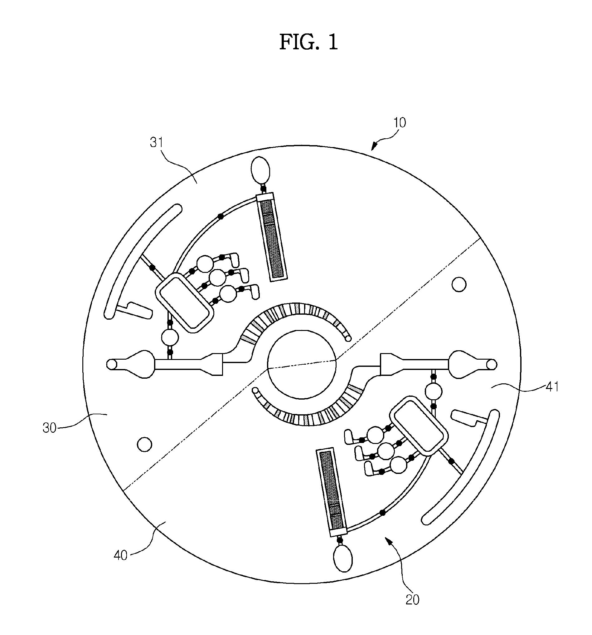
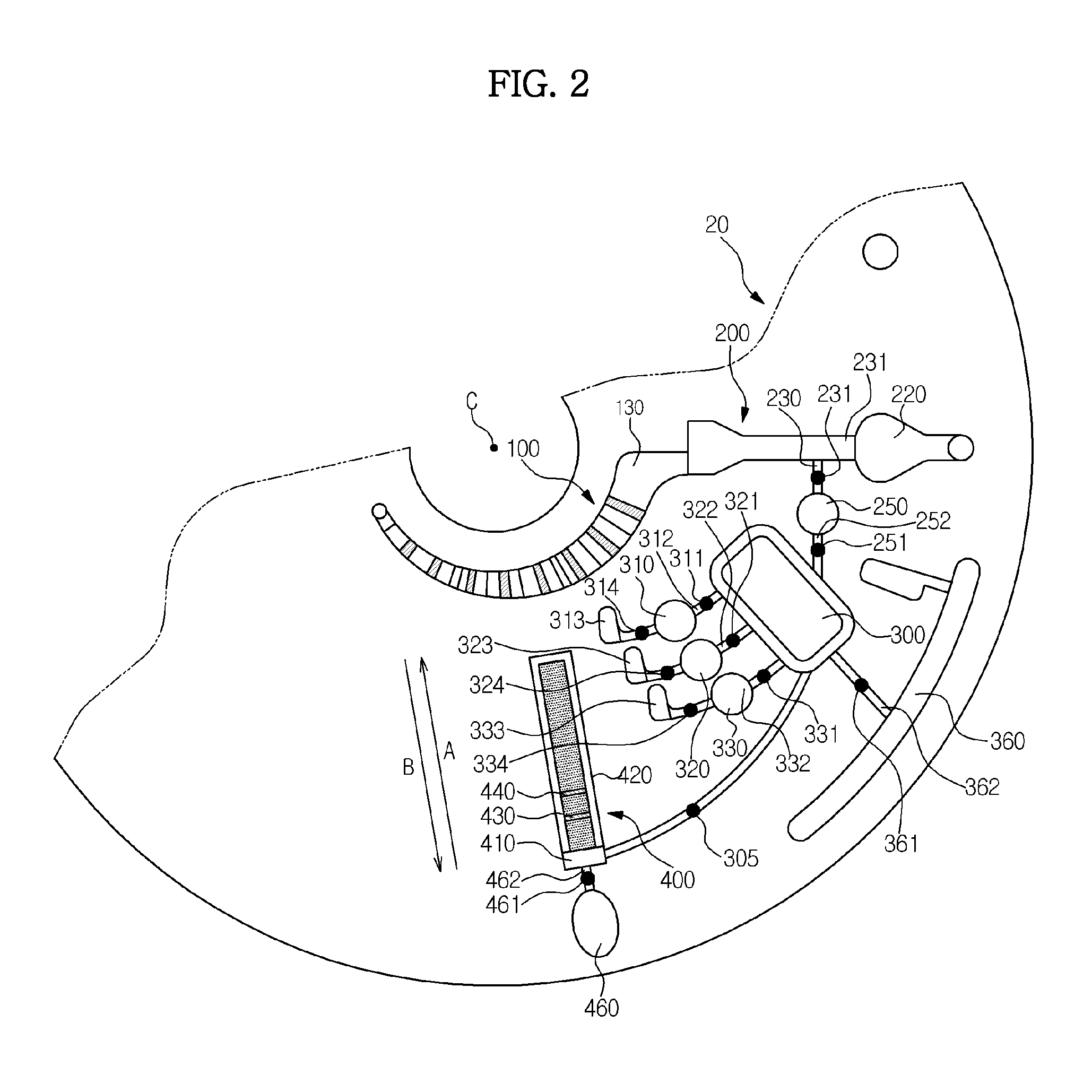
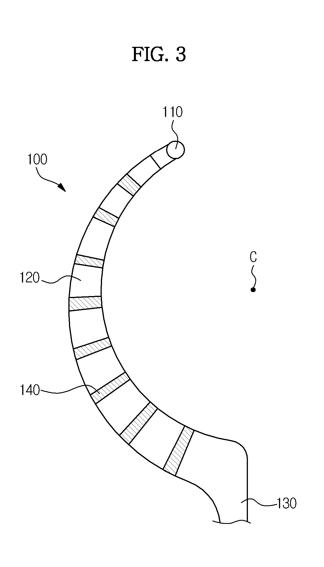
One exemplary embodiment provides a centrifugal micro-fluidic device for detection of an analyte from a liquid specimen, which includes a rotational body; at least one micro-fluidic structure having multiple chambers, at least one channel through which the multiple chambers are connected together and at least one valve for opening and closing the channel; and a detection unit, wherein the device also has a reaction chamber for receiving a detectable signal generator to be combined with the analyte in the liquid specimen and an analysis chamber that is located downstream of the reaction chamber and includes a detection region to which a capture binder to be combined with a detectable signal generator-analyte complex i...


PUM

PropertyMeasurementUnit
internal diameteraaaaaaaaaa
micro-fluidic structureaaaaaaaaaa
structuresaaaaaaaaaa

Abstract

A centrifugal micro-fluidic device detecting analytes in a liquid specimen and a method of detection of analytes from a liquid specimen using the micro-fluidic device are provided. Reaction efficiency is increased using a repetitive flow of the liquid specimen induced by an alternating combination of capillary force and centrifugal force, thereby enhancing detection sensitivity.

Description

BACKGROUND1. FieldApparatuses and methods consistent with exemplary embodiments relate generally to a centrifugal micro-fluidic device for detecting analytes in a liquid specimen and a detection method using the micro-fluidic device and, more particularly, to a centrifugal micro-fluidic device for detection of analytes from a liquid specimen with improved sensitivity. wherein a repeated flow of a liquid specimen induced by both capillary force and centrifugal force enhances reaction efficiency, as well as a method for detection of analytes in a liquid specimen using the micro-fluidic device.2. Description of the Related ArtIn order to cause a fluid to flow or move in a micro-fluidic structure of a micro-fluidic device, a driving pressure is generally required. The driving pressure may be a capillary pressure or pressure generated using an additional pump. In recent years, clinical diagnostic analyzers have been proposed that are designed to enable detection of a target material pres...

Claims


Application Information

Patent Timeline
Patent Type & Authority Applications(United States)
IPC IPC(8): G01N33/00
CPCB01L3/50273B01L3/502738B01L2200/10B01L2300/0806B01L2300/0867B01L2400/0406Y10T436/111666B01L2400/086B01L2400/088G01N33/54366G01N35/00069G01N2035/00495Y10T436/25375B01L2400/0409
Inventor KIM, IN WOOK
Owner SAMSUNG ELECTRONICS CO LTD
Why Eureka
Try Eureka