MRI-Safe Disc Magnet for Implants

a disc magnet and magnetic technology, applied in the field of magnetic elements, can solve the problems of not being strong enough to hold the external transmitter housing in the proper position, damage the adjacent tissue in the patient, and magnetic resonance imaging, so as to reduce friction and promote rotation

Active Publication Date: 2011-10-27
MED EL ELEKTROMEDIZINISCHE GERAETE GMBH
View PDF1 Cites 92 Cited by
  • Summary
  • Abstract
  • Description
  • Claims
  • Application Information

AI Technical Summary

Benefits of technology

[0009]The first attachment magnet may be adapted to rotate within the coil housing in response to an external magnetic field, and there may be a lubrication coating covering at least a portion of the first attachment magnet and reducing friction between the first attachment magnet and the coil housing to promote the rotation of the first attachment magnet. At least one of the attachment magnets may have a planar disc shape, a rectangular beam shape, a cylindrical beam shape, or a cut away disc shape. Or at least one of the attachment magnets may comprise a pair of complementary cylindrical attachment magnets, which optionally may further include a magnetic flux guide connecting the pair of complementary cylindrical attachment magnets.

Problems solved by technology

One problem arises when the patient undergoes Magnetic Resonance Imaging (MRI) examination.
Among other things, this may damage the adjacent tissue in the patient.
In addition, the external magnetic field from the MRI may reduce or remove the magnetization of the implant magnet 202 so that it may no longer be strong enough to hold the external transmitter housing in proper position.
The implant magnet 202 may also cause imaging artifacts in the MRI image, there may be induced voltages in the receiving coil, and hearing artifacts due to the interaction of the external magnetic field of the MRI with the implanted device.
This is especially an issue with MRI field strengths exceeding 1.5 Tesla.
Thus, for existing implant systems with magnet arrangements, it is common to either not permit MRI or at most limit use of MRI to lower field strengths.
But the spherical magnet arrangement requires a relatively large magnet much larger than the thickness of the other components of the implant, thereby increasing the volume occupied by the implant.
This in turn can create its own problems.
This is an additional step during implantation in such applications which can be very challenging or even impossible in case of very young children.

Method used


Image

  • MRI-Safe Disc Magnet for Implants
  • MRI-Safe Disc Magnet for Implants
  • MRI-Safe Disc Magnet for Implants

Examples


Embodiment Construction

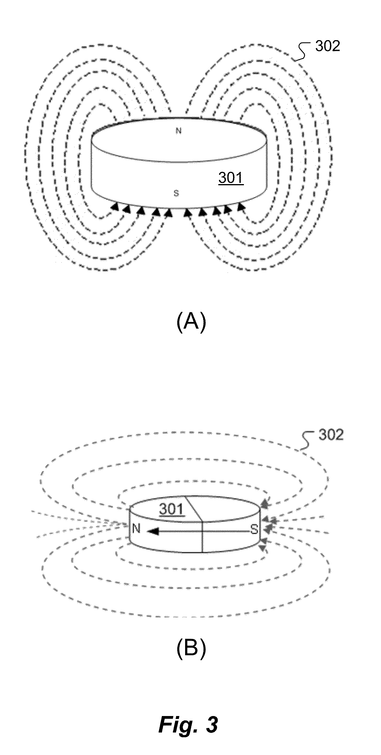
[0027]Various embodiments of the present invention are directed to a magnetic arrangement for an implantable system for a recipient patient which is compatible with MRI systems. FIG. 3A shows the magnetic field arrangement in typical existing implant attachment magnets. In this case, the attachment magnet 301 is disk-shaped (i.e., cylindrical) with the north-south magnetic dipole realized in the axial direction as is conventional producing magnetic field lines 302 as shown. Embodiments of the present invention change the direction of magnetization as shown in FIG. 3B so that the north-south magnetic dipole is oriented across the diameter of the attachment magnet 301 parallel to (i.e., “in”) the plane of the coil housing, producing magnetic field lines 302 as shown.

[0028]Of course, with such an arrangement, it is important that both the internal implant receiver attachment magnet and the external transmitter attachment magnet be magnetized with the same orientation in the plane of th...


PUM


Abstract

A magnetic arrangement is described for an implantable system for a recipient patient. A planar coil housing contains a signal coil for transcutaneous communication of an implant communication signal. A first attachment magnet is located within the plane of the coil housing and rotatable therein, and has a magnetic dipole parallel to the plane of the coil housing for transcutaneous magnetic interaction with a corresponding second attachment magnet.

Description

[0001]This application claims priority from U.S. Provisional Patent Application 61 / 327,158, filed Apr. 23, 2010, incorporated herein by reference.FIELD OF THE INVENTION[0002]The present invention relates to implantable medical devices, and specifically, to magnetic elements in such devices that allow for magnetic resonance imaging.BACKGROUND ART[0003]Some hearing implants such as Middle Ear Implants (MEI's) and Cochlear Implants (CI's) employ attachment magnets in the implantable part and an external part to hold the external part magnetically in place over the implant. For example, as shown in FIG. 1, a typical cochlear implant system may include an external transmitter housing 101 containing transmitting coils 102 and an external magnet 103. The external magnet 103 has a conventional coin-shape and a north-south magnetic dipole that is perpendicular to the skin of the patient to produce external magnetic field lines 104 as shown. Implanted under the patient's skin is a correspondi...

Claims


Application Information

Patent Timeline
Patent Type & Authority Applications(United States)
IPC IPC(8): A61N1/08
CPCA61N1/36032A61N1/37223A61N1/3718A61N1/36036A61N1/36038A61F2/18A61F2/20A61N1/37
Inventor ZIMMERLING, MARTINJAMNIG, BERNHARD
Owner MED EL ELEKTROMEDIZINISCHE GERAETE GMBH
Why Eureka
Try Eureka