Curve forming stent graft

a stent and curvature technology, applied in the field of medical devices, to achieve the effect of reducing the diameter, less points, and reducing the diameter

Active Publication Date: 2011-10-27
COOK MEDICAL TECH LLC +2
View PDF2 Cites 26 Cited by
  • Summary
  • Abstract
  • Description
  • Claims
  • Application Information

AI Technical Summary

Benefits of technology

[0018]In one embodiment the at least adjacent distal end points comprise immediately adjacent points and in an alternative embodiment the at least adjacent distal end points can comprise adjacent but one points. The former embodiment with immediately adjacent points is more useful where the stent is a nitinol stent because a nitinol stent usually has less points and pulling together the immediately adjacent points will give sufficient diameter reduction. The latter embodiment with adjacent but one points is more useful where the stent is a stainless steel stent because a stainless steel stent usually has more points and pulling together the adjacent but one points may be necessary give a sufficient diameter reduction.

Problems solved by technology

The problem with a curved lumen with significant continuing blood flow and such a staged release arrangement is that the proximal or leading edge of the stent graft particularly at the inner side of the curved lumen may not engage against the wall of the lumen and may fold in thereby blocking the desired flow path and allowing bypass to continue into the aneurysm.

Method used


Image

  • Curve forming stent graft
  • Curve forming stent graft
  • Curve forming stent graft

Examples


Embodiment Construction

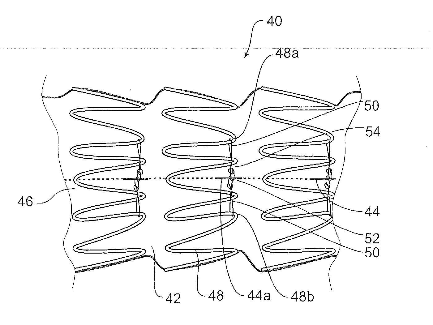
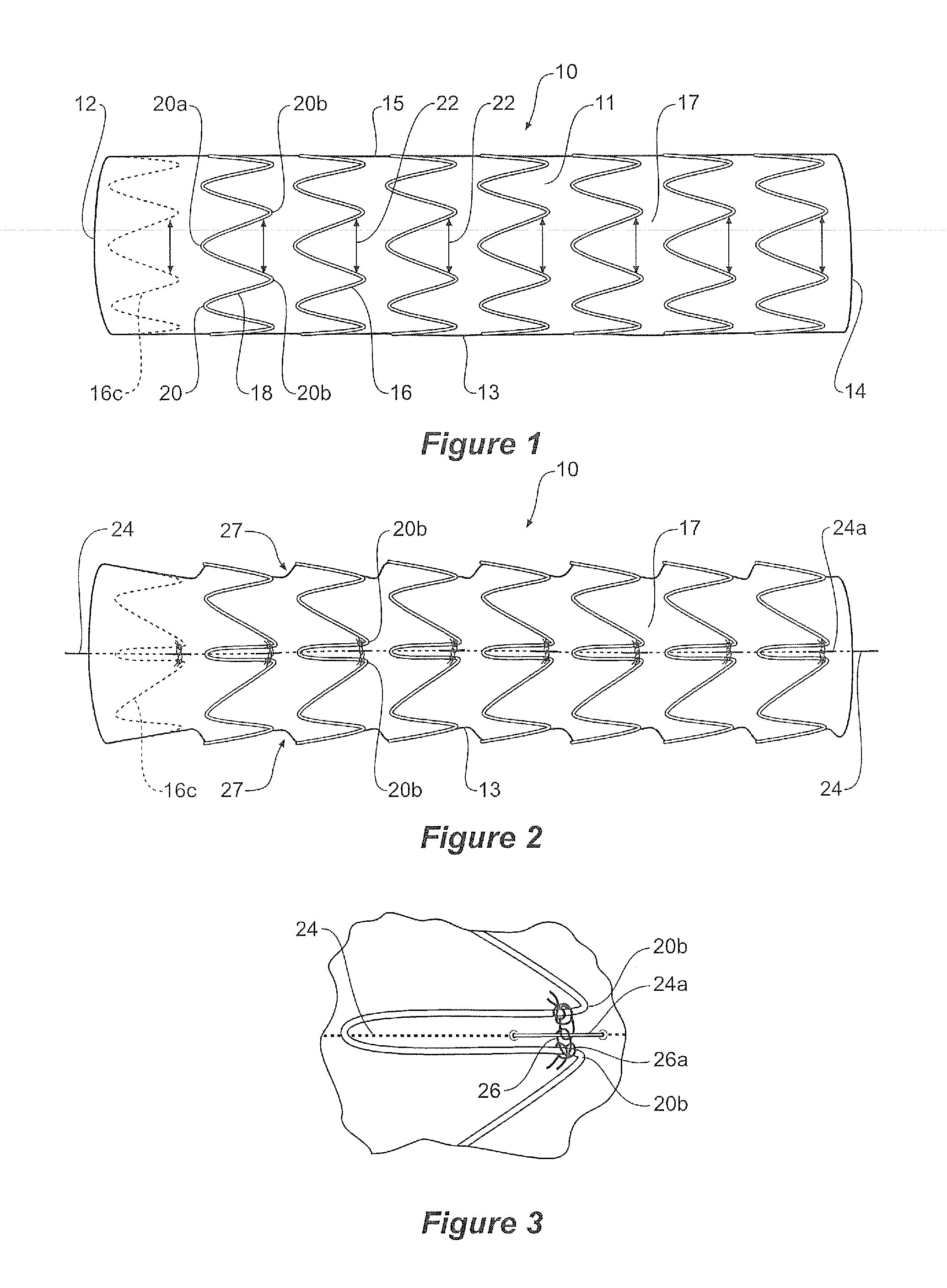
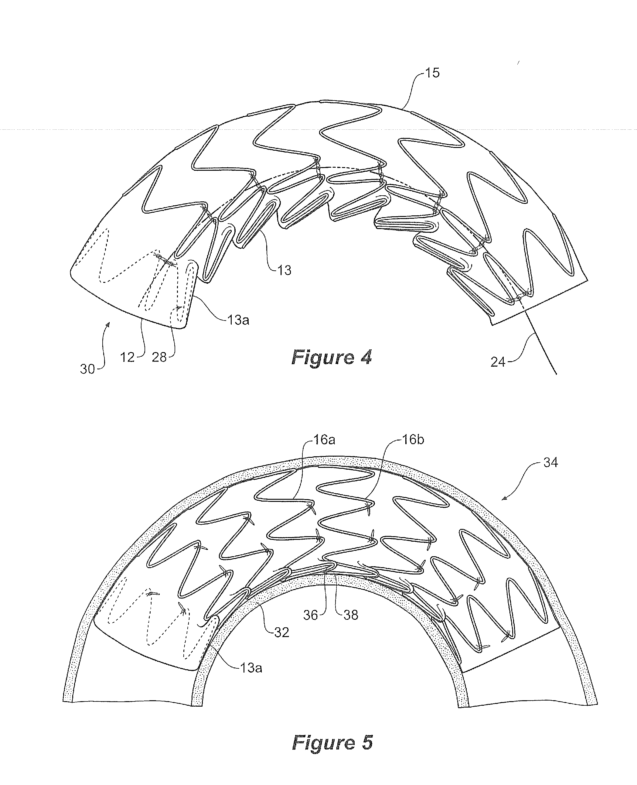
[0035]In the drawings a stent graft 10 comprises a tubular body of a biocompatible graft material 11. The tubular body has a first or proximal end 12 and a second or distal end 14. The stent graft has an inner curve side 13 which is the side which when the stent graft is deployed into a curved lumen is intended to be on the inside of the curve. The stent graft has an outer curve side 15 which is the side which when the stent graft is deployed into a curved lumen is intended to be on the outside of the curve. In between the inner and outer sides 13 and 15 is a lateral longitudinal side 17. A corresponding lateral longitudinal side is on the other side of the stent graft.

[0036]The stent graft is supported by a plurality of self expanding Gianturco style zig zag stents 16. Each stent 16 comprises a plurality of struts 18 and points 20 between adjacent struts and each stent is continuous around the tubular body. The points 20 comprise first end or proximal end points 20a and second end ...


PUM


Abstract

A curve forming stent graft for curved vessels such as the thoracic arch. The stent graft has a tubular body zig zag self expanding stents fastened to and supporting the tubular body. The zig zag self expanding stents comprising struts and points between adjacent struts thereby defining proximal end points and distal end points. A temporary diameter constriction arrangement associated with the least some of the plurality of zig zag self expanding stents comprises a pair of adjacent distal end points being releasably retained adjacent each other whereby at rest the tubular body of the stent graft is in a substantially sawtooth form and when released in a curved configuration a distal end point of a stent overlaps a proximal end point of a distally adjacent stent to facilitate curvature of the stent graft in a curved vessel.

Description

TECHNICAL FIELD[0001]This disclosure relates to a medical device and more particularly to a stent graft for mounting onto a deployment device for endovascular introduction into the vasculature of a patient.BACKGROUND[0002]This disclosure will be particularly discussed in relation to stent grafts for placement into the thoraco-abdominal aorta for the treatment of aneurysms and more specifically in relation to placement in a curved portion of the aorta such as the thoracic arch. The disclosure, however, is not so restricted and may be applied to stent grafts for placement in any lumen of the human or animal body.[0003]A stent graft is in a constricted form when it is delivered by endoluminal techniques to a deployment site within such a curved portion of the aorta. There have been devised diameter reducing arrangements for stent grafts so that there is a partial release stage of the stent graft after a covering sheath has been withdrawn. At this stage, the stent graft has expanded in ...

Claims


Application Information

Patent Timeline
Patent Type & Authority Applications(United States)
IPC IPC(8): A61F2/82
CPCA61F2/07A61F2002/075A61F2220/0075A61F2220/005A61F2/89
Inventor HARTLEY, DAVID ERNESTDUCKE, WERNER D.ROEDER, BLAYNE A.
Owner COOK MEDICAL TECH LLC
Why Eureka
Try Eureka