Thermal integration of a carbon dioxide capture and compression unit with a steam or combined cycle plant

a technology of carbon dioxide capture and compression unit and combined cycle plant, which is applied in the direction of steam engine plant, gas treatment, inorganic chemistry, etc., can solve the problems of large energy waste in water cooling towers or other water cooling facilities, large heat required for separation from post-combustion flue gas, and high energy consumption of separation processes, so as to facilitate the reduction of energy losses and increase the efficiency of the power plant.

Active Publication Date: 2011-11-03
GENERAL ELECTRIC TECH GMBH
View PDF3 Cites 27 Cited by
  • Summary
  • Abstract
  • Description
  • Claims
  • Application Information

AI Technical Summary

Benefits of technology

[0028]By this operation, the heating medium of the external heat cycle system is heated by means of surplus heat provided by the CO2 flow generated by the CO2 capture plant. The main heat exchanger for the external heating cycle system may again be operated at a lower load such that the steam extraction from the water steam cycle of the power plant can be reduced and the efficiency of the power plant consequently increased.
[0029]If the first, second, and / or third heat exchangers are arranged in series with the main heat exchanger, they are preferably arranged (with respect to the direction of flow in the external heat cycle system) upstream of the main heat exchanger. Such arrangement facilitates a reduction of the energy losses in the main heat exchanger as it functions on the basis of a pure condensing process (fixed temperature), while the first, second, and third heat exchangers operate on the basis of a subcooling process (decreasing temperature).

Problems solved by technology

This leaves a large portion of the energy wasted in the water cooling towers or other water cooling facilities.
On the other hand, CO2 separation from post-combustion flue gas requires a large amount of heat (in the form of steam).
CO2 separation processes thus are energy intensive.
The extraction of steam from the steam turbine reduces the electricity generation (output, overall efficiency).
For the same amount of steam, the higher the pressure (and thus the temperature) of the extracted steam is, the higher the loss of the electricity will be.
This energy cost, and the associated financial cost, inhibits the adoption of CO2 separation.
With conventional MEA-based absorption processes, the cost of CO2 separation from post-combustion flue gases requires a significant amount of the total CO2 sequestration cost.
High separation cost is the main reason for the delay in CO2 emission control.
High CO2 separation cost is also hindering the acceptance of CO2 based Enhanced Oil Recovery technology.
The implementation of a CO2 capture and compression system on a combined cycle or steam power plant leads to a drop of its overall efficiency.

Method used


Image

  • Thermal integration of a carbon dioxide capture and compression unit with a steam or combined cycle plant
  • Thermal integration of a carbon dioxide capture and compression unit with a steam or combined cycle plant
  • Thermal integration of a carbon dioxide capture and compression unit with a steam or combined cycle plant

Examples


Embodiment Construction

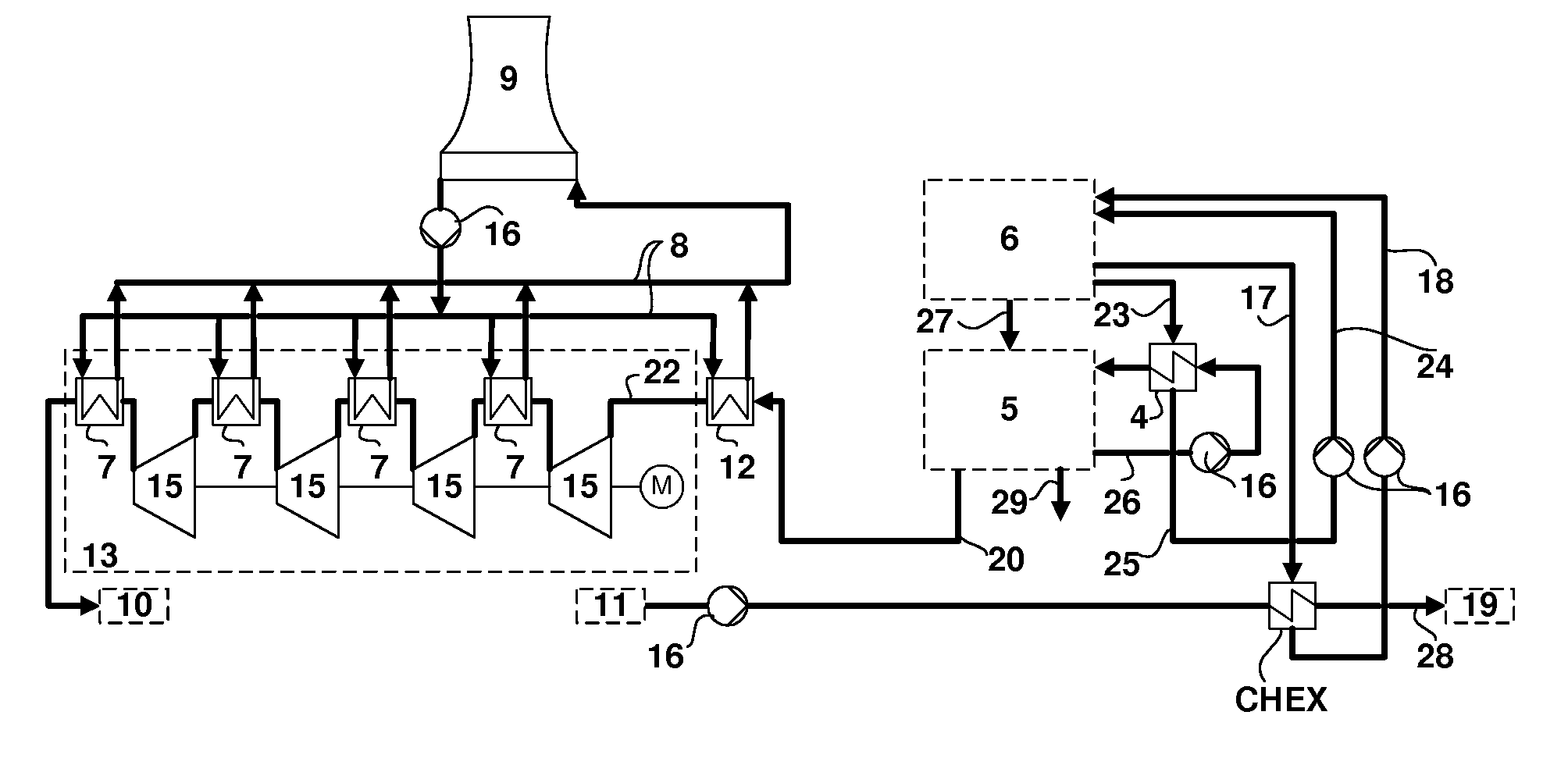
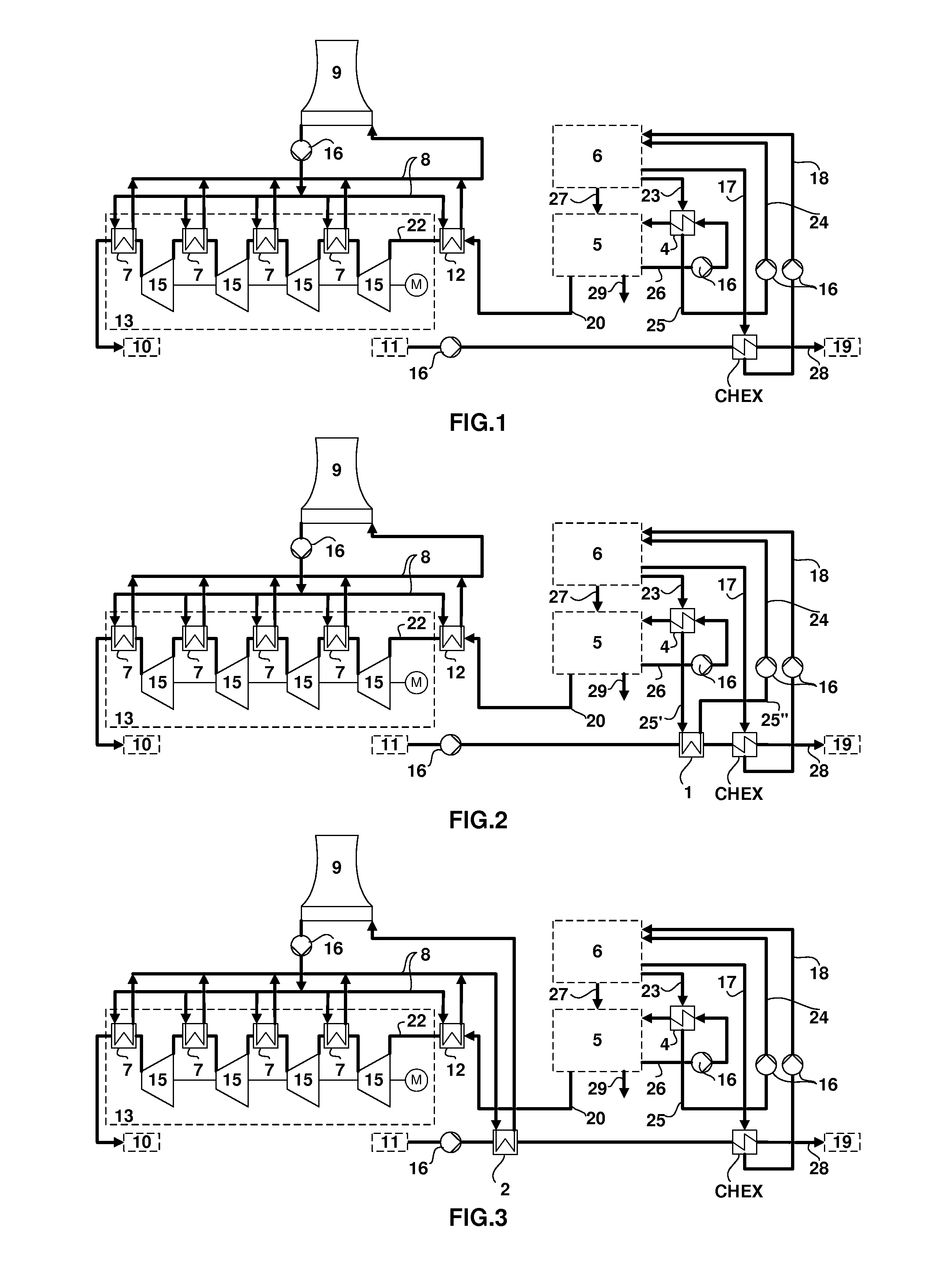
[0055]FIG. 2 shows a power plant 6 with a CO2 capture plant 5 having a line 27 for flue gas leading from the power plant to the CO2 capture plant 5, a line 20 leading the extracted CO2 away from the capture plant 5, and a line 29 releasing flue gas free of CO2. An absorber solution cycle includes a line 26 for the absorber solution leading from the capture plant to a reboiler 4 for the absorber solution. A steam extraction line 23 directs steam for the operation of the reboiler 4 from the power plant's water steam cycle, for example from the heat recovery steam generator, and a line 25 leads return condensate away from the reboiler 4. The line 20 for the CO2 extracted extends from the CO2 capture plant to a precooler 12, which is arranged prior to the CO2 compression unit 13.

[0056]The power plant of FIG. 2 includes an integration of the power plant and CO2 capture and compression and cooling system with an external heat cycle system. The heat cycle system includes a cycle line 28 fo...


PUM

PropertyMeasurementUnit
temperatureaaaaaaaaaa
pressureaaaaaaaaaa

Abstract

A power plant system including a fossil fuel fired power plant (6) for the generation of electricity, a carbon dioxide capture and compression system (5, 13), and an external heat cycle system has at least one heat exchanger (1,2,3) for the heating of the flow medium of the external heat cycle system. The heat exchanger (1,2,3) is connected to a heat flow from the CO2 capture plant (5) or a CO2 compression unit (13). A return flow from the heat exchanger (1,2,3) is led to the CO2 capture and compression system (5,13) or to the power plant (6). The power plant system allows an increase in overall efficiency of the system.

Description

[0001]This application claims priority under 35 U.S.C. §119 to European App. No. 10161290.1, filed 28 Apr. 2010, the entirety of which is incorporated by reference herein.BACKGROUND[0002]1. Field of Endeavor[0003]The present invention relates to a method for the operation of a power plant system having a power plant for the generation of electricity, in particular of a combined cycle power plant or a steam power plant operated with fossil fuels, a carbon dioxide capture and compression system, and an external heat cycle system. It furthermore relates to a power plant system useful for practicing the method.[0004]2. Brief Description of the Related Art[0005]Conventional fossil fuel-burning power plants use a steam cycle for power generation, in the case of the use of gas turbines, in a so-called combined cycle power plant, in combination with gas turbines. Steam cycles are also used in newer power plants, such as Integrated Gasification Combined Cycle (IGCC) power plants or Natural G...

Claims


Application Information

Patent Timeline
Patent Type & Authority Applications(United States)
IPC IPC(8): F01K13/00F01K3/26C01B32/50
CPCY02E20/14F01K17/02Y02C20/40Y02E20/16Y02E20/18Y02E20/32B01D53/14B01D53/1475B01D2257/504B01D2259/65F01K13/00F01K17/04F01K17/06F01K23/10F02C3/34F02C6/18
Inventor DROUVOT, PAULLI, HONGTAODIETZMANN, JORG
Owner GENERAL ELECTRIC TECH GMBH
Why Eureka
Try Eureka