Inherently torque limiting magnetically-coupled wheels

a magnetically coupled, inherently torque-limiting technology, applied in the direction of dynamo-electric machines, air transport, electrical apparatus, etc., can solve the problems of friction wear, parts jamming, loss of lubrication,

Active Publication Date: 2011-11-03
WHITFIELD GEORGE WINSTON +1
View PDF10 Cites 22 Cited by
  • Summary
  • Abstract
  • Description
  • Claims
  • Application Information

AI Technical Summary

Benefits of technology

[0021]A preferred embodiment of the invention, which is incorporated in other embodiments of the invention, comprises a driving rotational object having magnet supporting surface which supports a series of adjacent magnets of opposite polarity, the driving rotational component being adjacent to at least one driven rotational object and having a magnet supporting edge including a set of adjacent magnets having opposite polarities. An external motor torque rotates the driving rotational object. The driving rotational object passes its magnets through a first location and the driven object passes its magnets through a second location spaced from the first location, but the first and second locations are withi

Problems solved by technology

The problem with such physical contact is that there is often the problem of jamming of the parts, the problem of deleterious particles and matter getting between the parts, loss of lubrication and the wearing down by friction.
Propulsion syste

Method used


Image

  • Inherently torque limiting magnetically-coupled wheels
  • Inherently torque limiting magnetically-coupled wheels
  • Inherently torque limiting magnetically-coupled wheels

Examples


Embodiment Construction

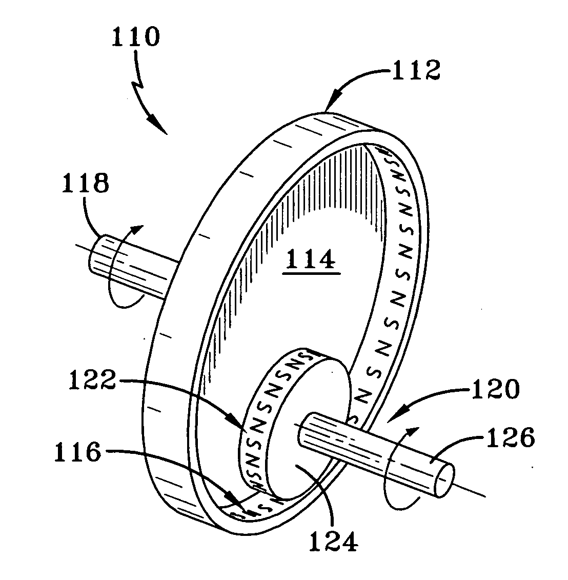
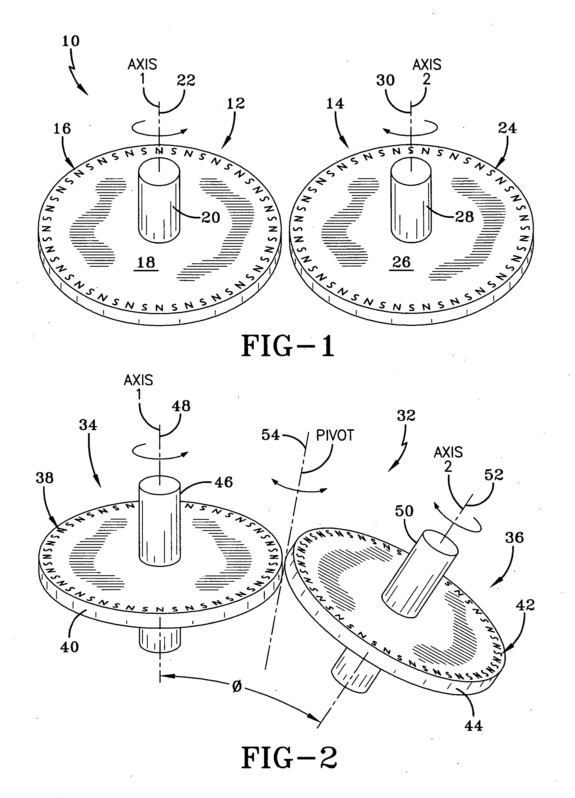
[0040]Referring first to FIG. 1, a magnetic gear train 10 is shown (as noted earlier, magnetic wheels are being referred to as magnetic gears). Magnetic gear train 10 comprises a first magnetic gear 12 and a cooperating magnetic gear 14. Magnetic gear 12 has along it periphery a series of magnets of alternating polarity, north (N) and south (S), which are collectively identified by the numeral 16, and can constitute a series of magnets embedded in the edge of a disk 18 of which magnetic gear 12 is comprised. Magnetic gear 12 has an axle 20 and a longitudinal pivot axis 22. Magnetic gear 14 has a series of alternating magnets identified collectively by the numeral 24 embedded in a disk 26 forming part of magnetic gear 14. An axle 28 rotates magnetic gear 24 about a longitudinal axis 30. Assuming magnetic gear 12 is the driving gear, some means such as a battery powered electric motor or other external motor torque is used to rotate magnetic gear 12 counter clockwise when viewed from ...


PUM


Abstract

An apparatus having at least one rotatable driven object having an edge on which are disposed a series of adjacent magnets of alternating polarity and a driving object rotatable by an external motor torque and having a series of adjacent magnets of alternating polarity on a magnet supporting surface. The magnet supporting surface of the driving object is rotatable through a common region approximately centered about the point of closest approach to the magnet supporting edge of the driven object for sequentially placing magnets of the driving object in the region enveloping the effective interactive range between the two objects. The fields of magnets of opposite polarity of the driving object interact with the fields of the magnets on the driving object to effect rotation of the driven object. Disclosed are structures for torque limiting wheels, magnetic gear trains, reduction gears and ball joints, and propulsion systems for watercraft and aircraft.

Description

CROSS-REFERENCE TO RELATED APPLICATION[0001]This application claims priority of U.S. Provisional Application No. 61 / 343,395 filed Apr. 28, 2010, under Title 35, United States Code, Section 119(e), which is incorporated herein by reference in its entirety.BACKGROUND OF THE INVENTION[0002]1. Field of the Invention[0003]This invention relates to magnetically coupled wheels (sometimes referred to as magnetic gears) and rotating objects, and in particular to a magnetically driven set of wheels or rotating objects which are not to be physically engaged by the respective driving wheels or driving objects and can operate at a spaced distance from the respective driving wheels or driving objects, as well as operating other components operated by the driven wheels or driven rotating objects.[0004]2. Description of the Prior Art[0005]Many devices function by having at least one rotating member for engagement with another member. The problem with such physical contact is that there is often the...

Claims


Application Information

Patent Timeline
IPC IPC(8): H02K49/10
CPCB63H23/22B64D27/24Y02T50/62H02K49/102B64D35/02Y02T50/60
Inventor WHITFIELD, GEORGE WINSTONCHIN, HOWARD MARTIN
Owner WHITFIELD GEORGE WINSTON
Why Eureka
Try Eureka