Liquid crystal display apparatus and backlight

a liquid crystal display and backlight technology, applied in the direction of illuminated signs, display means, instruments, etc., can solve the problems of affecting the driving operation of the driver, and achieve the effects of improving light utilization efficiency, low luminance display, and high luminance display

Inactive Publication Date: 2011-11-03
SHARP KK
View PDF6 Cites 54 Cited by
  • Summary
  • Abstract
  • Description
  • Claims
  • Application Information

AI Technical Summary

Benefits of technology

[0036]A liquid crystal display device of the present invention can provide display in such a manner that the luminance is relatively uniform and high in specific directions while the luminance is extremely low in the other directions, so that light utilization efficiency improves. In the liquid crystal display device of the present invention, the intermediate luminance region ranging between the region in which high luminance display is provided and the region in which low luminance display is provided can be narrowed. Therefore, display with high light utilization efficiency can be provided such that display light is concentrated in a desired range. When a liquid crystal display device of the present invention is installed in a vehicle, high quality display can be provided to passengers, while reflection of images in the side door's glass, and the like, can be reduced.

Problems solved by technology

As a result, in FIG. 14, reflected images 4A and 4B of the display occur in the windshield 5 or the door glass 6, which may disadvantageously impede the driving operation of the driver 1.

Method used


Image

  • Liquid crystal display apparatus and backlight
  • Liquid crystal display apparatus and backlight
  • Liquid crystal display apparatus and backlight

Examples


embodiment 1

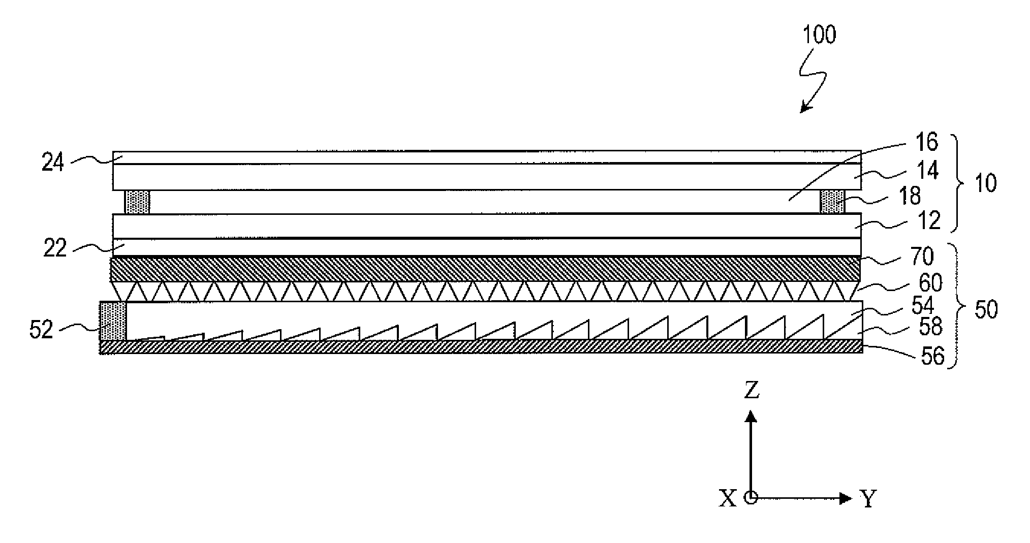
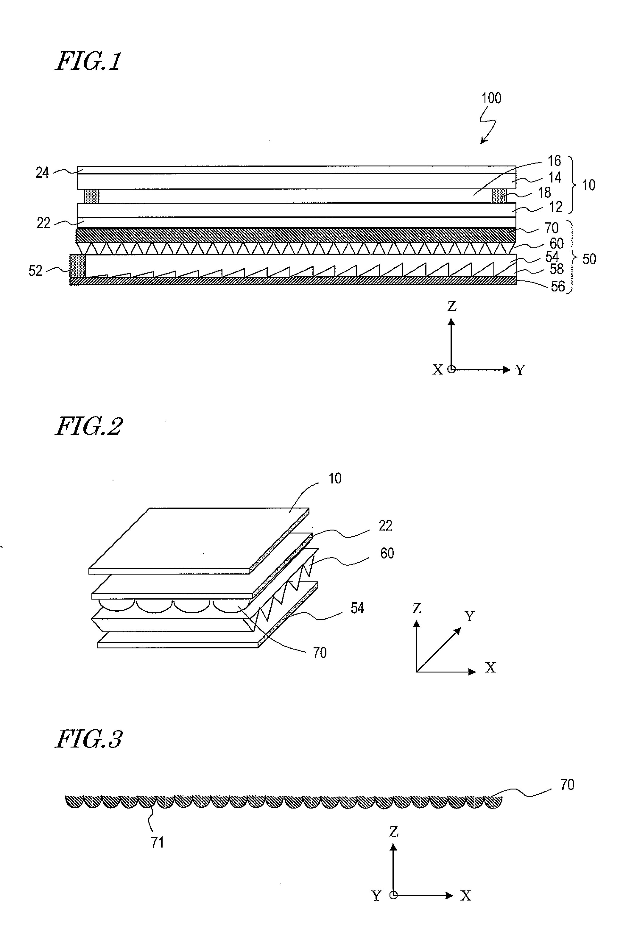
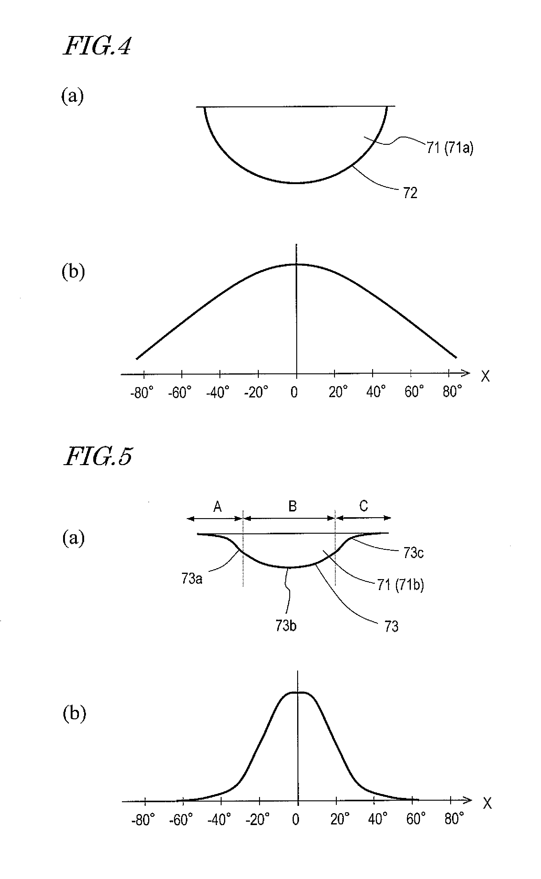
[0054]FIG. 1 is a cross-sectional view schematically showing the configuration of a liquid crystal display device 100 of Embodiment 1 of the present invention. FIG. 2 is a perspective view schematically showing the configuration of the liquid crystal display device 100. FIG. 3 is a cross-sectional view schematically showing the shape of an optical sheet 70 of the liquid crystal display device 100. The liquid crystal display device 100 is a liquid crystal display device which is suitable to onboard applications, although the uses thereof are not limited to onboard applications.

[0055]The liquid crystal display device 100 is an active matrix type transmissive liquid crystal display device (LCD). The liquid crystal display device 100 may be a transflective liquid crystal display device. The liquid crystal display device 100 has a plurality of pixels which are arranged in a matrix along the X direction (second direction) and the Y direction (first direction) which are perpendicular to ea...

embodiment 2

[0091]FIG. 11 is a cross-sectional view schematically showing the configuration of a liquid crystal display device 101 of Embodiment 2 of the present invention. FIG. 12 is a cross-sectional view schematically showing the shape of a microlens array 82 of the liquid crystal display device 101. FIG. 13 shows the viewing angle characteristic in the Y direction which is achieved by the liquid crystal display device 101. The ordinate axis of FIG. 13 represents the luminance, and the abscissa axis represents the polar angle where the Z direction is 0°.

[0092]The liquid crystal display device 101 is also an active matrix type transmissive or transflective liquid crystal display device which is suitable to onboard applications, as is the liquid crystal display device 100 of Embodiment 1. The liquid crystal display device 101 has a plurality of pixels which are arranged in a matrix along the X direction (second direction) and the Y direction (first direction) which are perpendicular to each ot...


PUM

PropertyMeasurementUnit
central angleaaaaaaaaaa

Abstract

The present invention provides display with high light utilization efficiency, with increased luminance being provided in desired directions.
A liquid crystal display device of the present invention has a plurality of pixels arranged in a matrix along a first direction and a second direction which are perpendicular to each other, and includes: a TFT substrate; a counter substrate; a liquid crystal layer interposed between the TFT substrate and the counter substrate; an optical film including a polarizer provided on a surface of the TFT substrate which is opposite to the liquid crystal layer; and a backlight provided on a side of the optical film which is opposite to the TFT substrate, wherein the backlight includes an optical element layer provided on a side of the light guide plate which is closer to the optical film, and the optical element layer includes a plurality of lenticular lenses extending in the first direction, each of the lenticular lenses having a light receiving surface protruding toward the light guide plate.

Description

TECHNICAL FIELD [0001]The present invention relates to a backlight and a liquid crystal display device which performs display using a backlight.BACKGROUND ART [0002]In recent years, liquid crystal display devices are widely used as display devices for monitors, projectors, mobile information terminals, mobile phones, and the like. Generally speaking, a liquid crystal display device allows the transmittance (or reflectance) of a liquid crystal panel to vary with a driving signal, thus modulating the intensity of light from a light source for irradiating the liquid crystal panel, whereby images and text characters are displayed. Liquid crystal display devices include direct-viewing type display devices in which images or the like that are displayed on the liquid crystal panel are directly viewed, projection-type display devices (projectors) in which displayed images are projected onto a screen through a projection lens in an enlarged size, and so on.[0003]By applying a driving voltage...

Claims


Application Information

Patent Timeline
Patent Type & Authority Applications(United States)
IPC IPC(8): G02F1/13357G02F1/1335
CPCG02B6/0053G02F2001/133607G02F1/133606G02F1/133607
Inventor USUKURA, NARU
Owner SHARP KK
Why Eureka
Try Eureka