Characteristic image extraction method and ophthalmologic apparatus

Active Publication Date: 2011-11-03
CANON KK
View PDF5 Cites 22 Cited by
  • Summary
  • Abstract
  • Description
  • Claims
  • Application Information

AI Technical Summary

Benefits of technology

[0012]The present invention has been made in view of the above-mentioned situations, and an object thereof is to alleviate inefficiency exhibited at a time of reacquiring characteristic points for eye movement detection when an imaging target region of an eye to be inspected is changed due to a movement of a fixation index.

Problems solved by technology

The increase in the speed allows three-dimensional image taking of the fundus, which has been difficult with the time domain method, to be carried out.
However, in the three-dimensional image taking, two-dimensional scanning of the fundus is necessary even with the Fourier domain method, and hence an influence of an involu

Method used


Image

  • Characteristic image extraction method and ophthalmologic apparatus
  • Characteristic image extraction method and ophthalmologic apparatus
  • Characteristic image extraction method and ophthalmologic apparatus

Examples


Example

First Embodiment

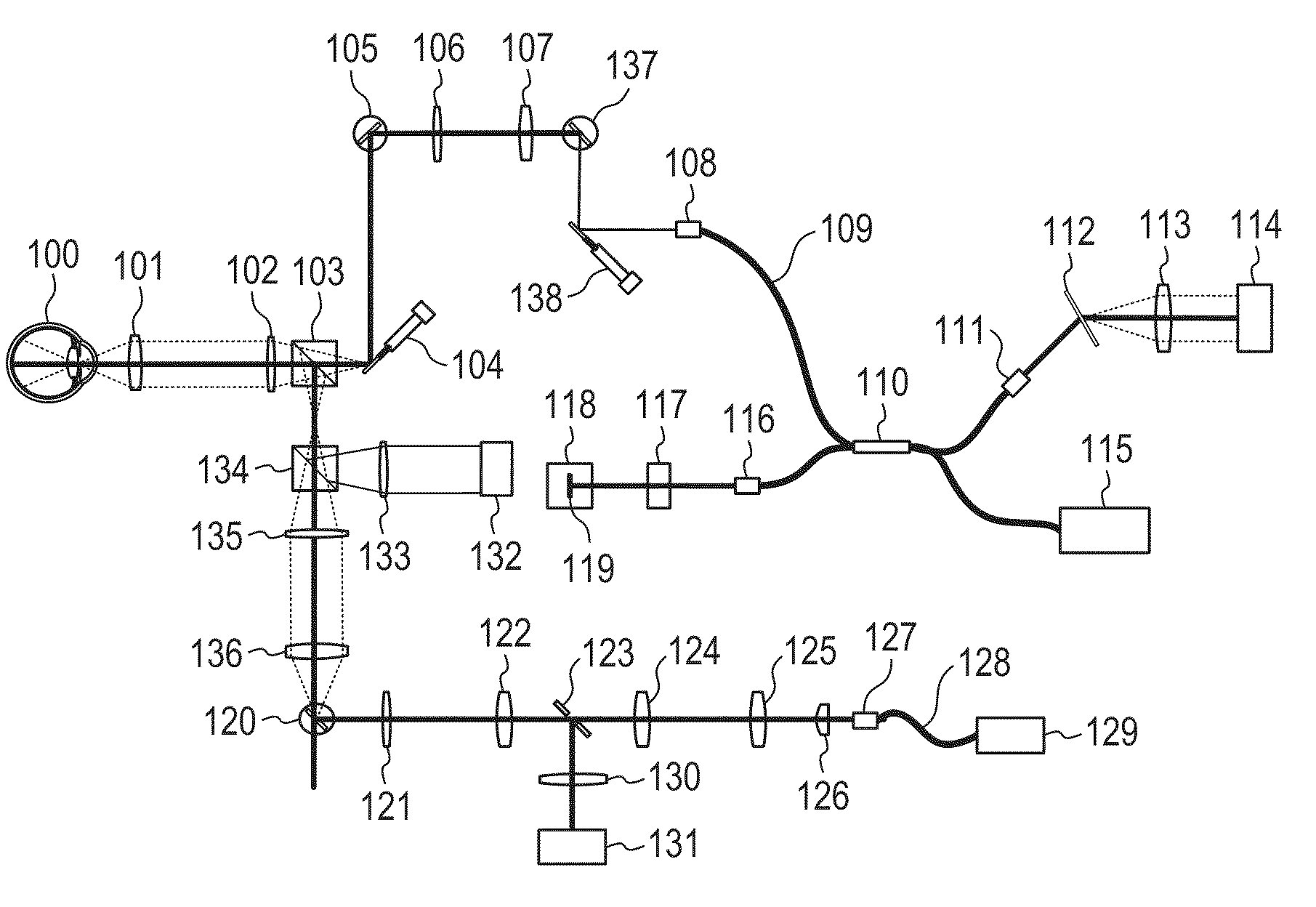
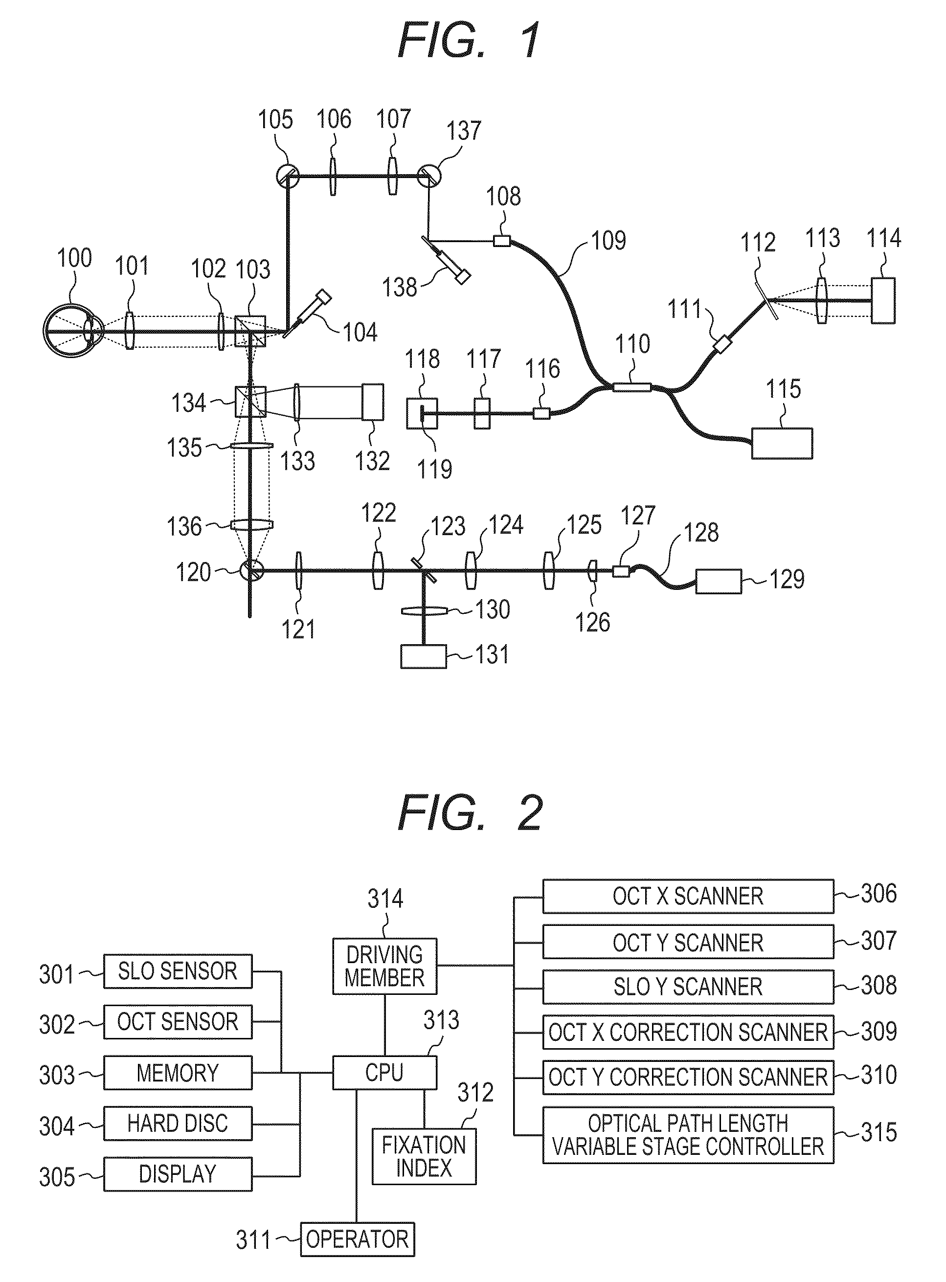
[0023]A first embodiment is described by taking a case where the present invention is applied to an OCT apparatus with a tracking function for extracting templates (also referred to as “first characteristic points or first characteristic images”) from a fundus image (also referred to as “first fundus image”), subjecting a newly (continuously) taken fundus image (also referred to as “second fundus image”) to pattern matching (retrieving the extracted characteristic images from the newly taken fundus image) to thereby detect an eye movement, and correcting an OCT beam. The description is made with reference to an optical structure diagram of FIG. 1 illustrating the OCT apparatus with a tracking function using a line-scan SLO, a block diagram of FIG. 2 illustrating the OCT apparatus with a tracking function using a line-scan SLO, and diagrams of FIGS. 3 and 4 illustrating fundus images.

[0024]In a tracking technology performed in this embodiment, a movement in a directio...

Example

Second Embodiment

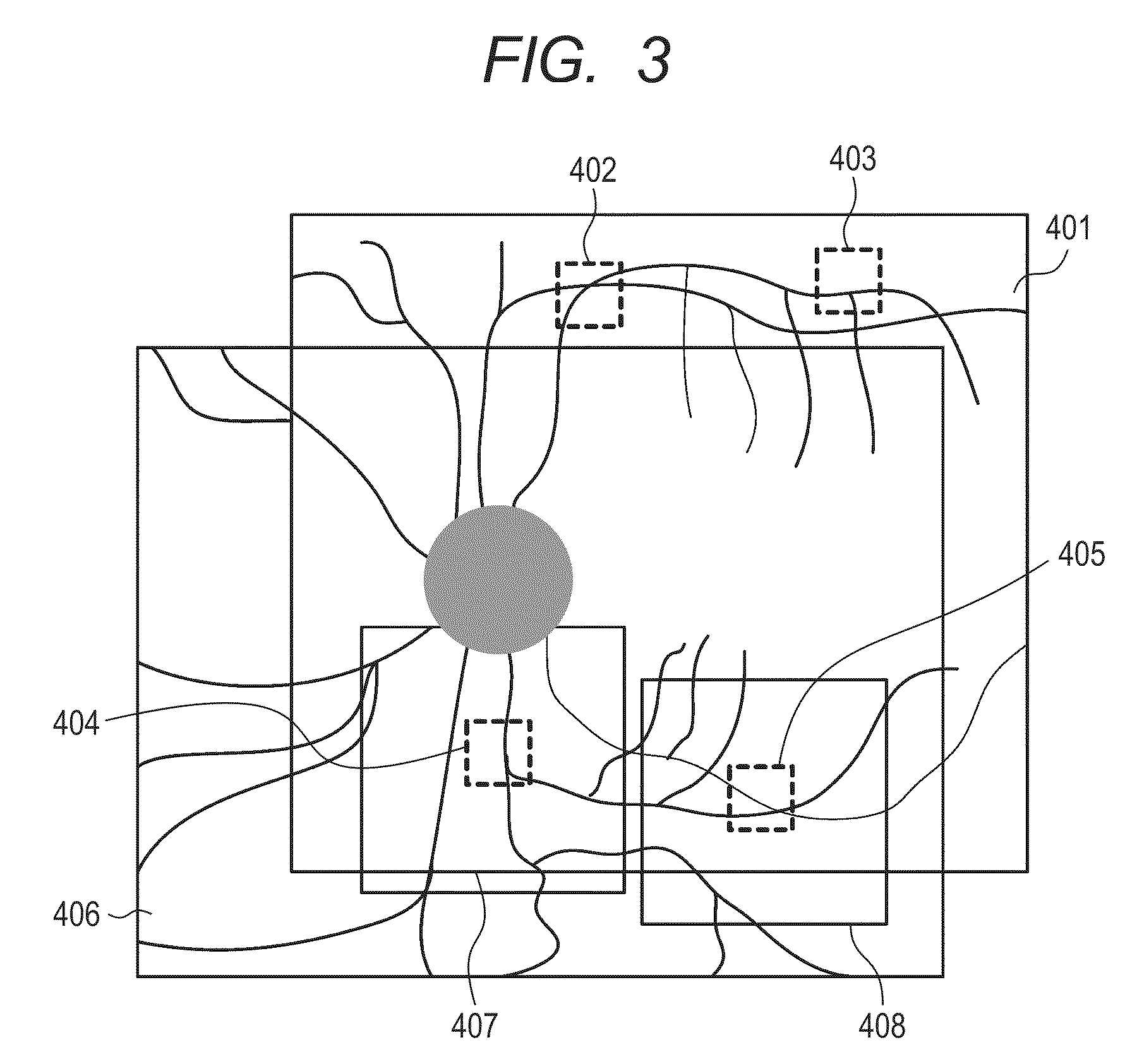
[0053]In the first embodiment, the range for reacquiring templates after the movement of the fixation index is limited to the remaining part of the SLO image 406 acquired after the movement of the fixation index except the above-mentioned peripheries 407 and 408 of the templates 404 and 405, respectively, remaining within the SLO image 406 acquired after the movement of the fixation index among the existing templates 402, 403, 404, and 405. This is not essential conditions, and a configuration of a second embodiment may be employed.

[0054]The optical system including the SLO and the OCT apparatus is the same as that of the first embodiment. The method of performing the tracking of an OCT based on the SLO image is also the same. Only an algorithm for reacquiring the templates when the fixation index is moved is different.

[0055]The second embodiment is described with reference to a conceptual diagram of FIG. 4 illustrating a relationship between the SLO images and the ...


PUM


Abstract

Provided is an ophthalmologic apparatus for detecting an eye movement from movements of a plurality of characteristic points within a fundus image. It is determined whether or not the plurality of characteristic points are included in a new fundus image when a position of a fixation index is changed, based on a relationship between a displacement amount of the fixation index and positions of the characteristic points within a fundus plane. If it is determined that at least one of the plurality of characteristic points is not included in the new fundus image, new characteristic points are extracted from a limited range within a new fundus plane image. Accordingly, the characteristic points can be efficiently reacquired for eye movement detection performed when an imaging target region of an eye to be inspected is changed by the fixation index.

Description

BACKGROUND OF THE INVENTION[0001]1. Field of the Invention[0002]The present invention relates to a characteristic image extraction method and an ophthalmologic apparatus, in particular, a characteristic image extraction method and an ophthalmologic apparatus which involve a devised tracking function working when a fixation index is moved.[0003]2. Description of the Related Art[0004]At present, various optical equipments are used as ophthalmologic apparatuses or ophthalmic equipments. Of those, used as an optical equipment for observing an eye are various equipments including an anterior ocular segment photographing device, a fundus camera, a confocal scanning laser ophthalmoscope (SLO), and an optical coherence tomography (OCT) apparatus that is an optical tomographic imaging apparatus using optical interference due to low coherence light. In particular, the OCT apparatus using the optical interference due to the low coherence light is an apparatus for obtaining a tomographic image ...

Claims


Application Information

Patent Timeline
IPC IPC(8): A61B3/14G06K9/00
CPCG06K9/00597G06T7/0081A61B3/1025A61B3/0091A61B3/102G06T2207/30041G06T7/11G06V40/18
Inventor NAKAJIMA, JUNKOUTSUNOMIYA, NORIHIKO
Owner CANON KK
Why Eureka
Try Eureka