
Unidirectional absolute optical attenuation measurement with otdr

an optical attenuation measurement and absolute optical technology, applied in the direction of optical elements, instruments, transmission monitoring, etc., can solve the problems of noisy signal, difficult to monitor the change in attenuation of each line, and complicated interpretation of otdr measurements

Inactive Publication Date: 2011-11-03
COMMSCOPE CONNECTIVITY BELGIUM BVBA
View PDF29 Cites 28 Cited by
  • Summary
  • Abstract
  • Description
  • Claims
  • Application Information

AI Technical Summary

Benefits of technology

[0012]Optical measurement methods and devices according to embodiments of the present invention are suitable for both point to point and point to multipoint networks. These are based on returning signals, e.g. from reflective points in the network and are based on amplitude measurents of returning signals, e.g. reflections, from know devices.
[0015]Optical measurement methods and devices according to embodiments of the present invention do not interfere with the data transmission when wavelength selective devices are used, e.g. reflectors.
[0016]Optical measurement methods and devices according to embodiments of the present invention are not influenced by changes in other branches after the.
[0017]Optical measurement methods and devices according to embodiments of the present invention can be used in centralized or distributed splitter PON.
[0018]Optical measurement methods and devices according to embodiments of the present invention can be used in G-PON networks with split levels up to 64 or higher.
[0025]A machine readable signal storage device can store the computer program product, e.g. a CD-ROM or similar.

Problems solved by technology

One problem is that the interpretation of the OTDR measurements is quite complicated or sometimes even impossible on point to multipoint networks for the following reasons.
This makes it extremely complicated to monitor the change in attenuation of each line, certainly when the network changes over time.
Beyond the splitter the signal becomes noisy due to the lack of dynamic range.
No accurate information can be obtained from this noisy baseline.
This can means that it is not possible to set alarms reliably.

Method used


Image

  • Unidirectional absolute optical attenuation measurement with otdr
  • Unidirectional absolute optical attenuation measurement with otdr
  • Unidirectional absolute optical attenuation measurement with otdr

Examples


Embodiment Construction

[0031]The present invention will be described with respect to particular embodiments and with reference to certain drawings but the invention is not limited thereto but only by the claims. The drawings described are only schematic and are non-limiting. In the drawings, the size of some of the elements may be exaggerated and not drawn on scale for illustrative purposes. Where the term “comprising” is used in the present description and claims, it does not exclude other elements or steps. Where an indefinite or definite article is used when referring to a singular noun e.g. “a” or “an”, “the”, this includes a plural of that noun unless something else is specifically stated.

[0032]The term “comprising”, used in the claims, should not be interpreted as being restricted to the means listed thereafter; it does not exclude other elements or steps. Thus, the scope of the expression “a device comprising means A and B” should not be limited to devices consisting only of components A and B. It ...


PUM


Abstract

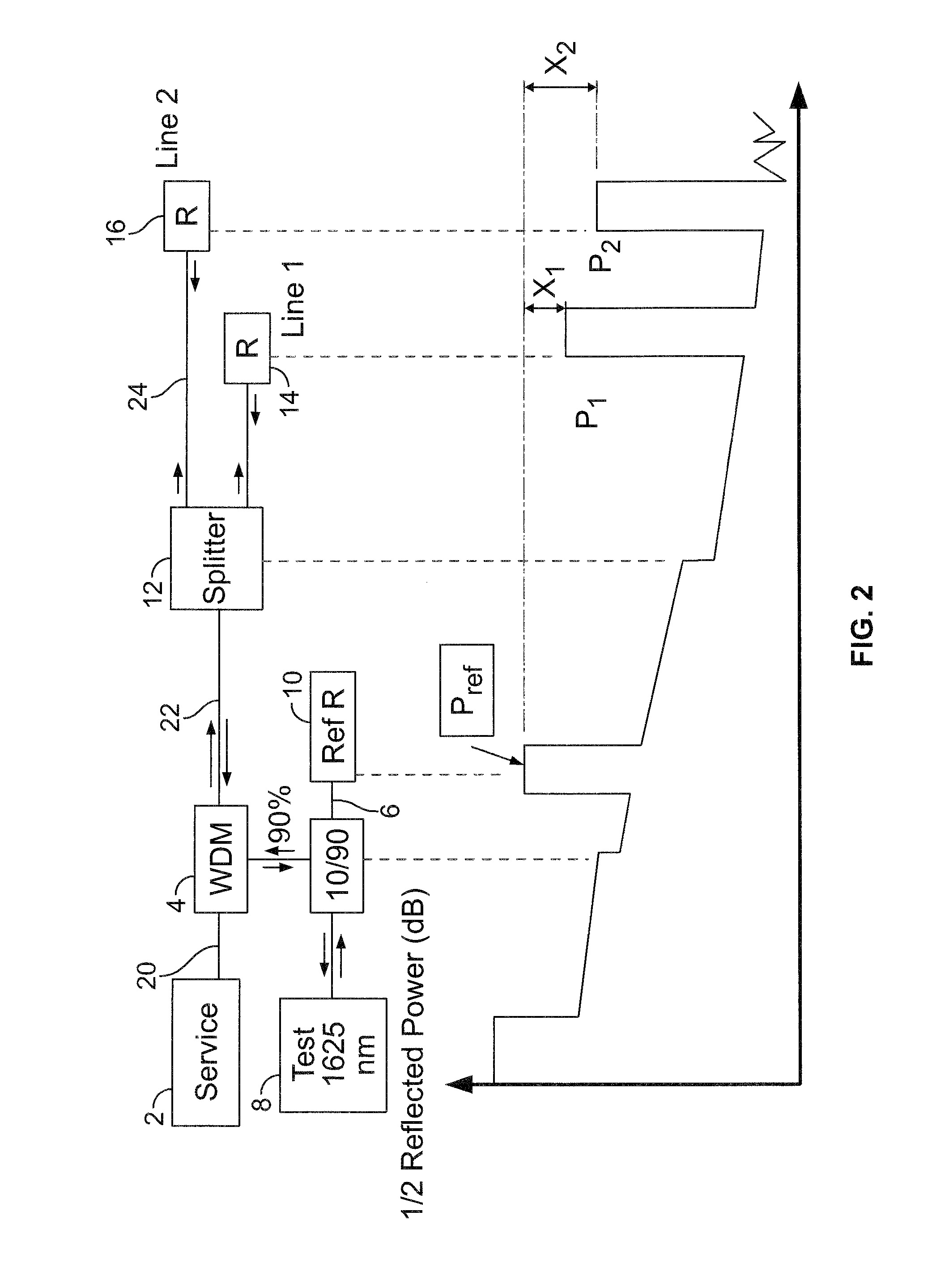
Devices and methods for optical measurements in point-to-point and point-to-multipoint networks, e.g. like PON networks with splitters are described in which reflected power from some known reflections at the end of the lines is used to determine the attenuation and stability of the attenuation of each line. Also a reference reflection is used at the beginning of the network so that an absolute loss measurement between the points of reflection and the reference reflection can be made. In a further aspect wavelength selective stable reflections and reflectors are used, to provide reflections in a wavelength range that does not interfere with normal operation.

Description

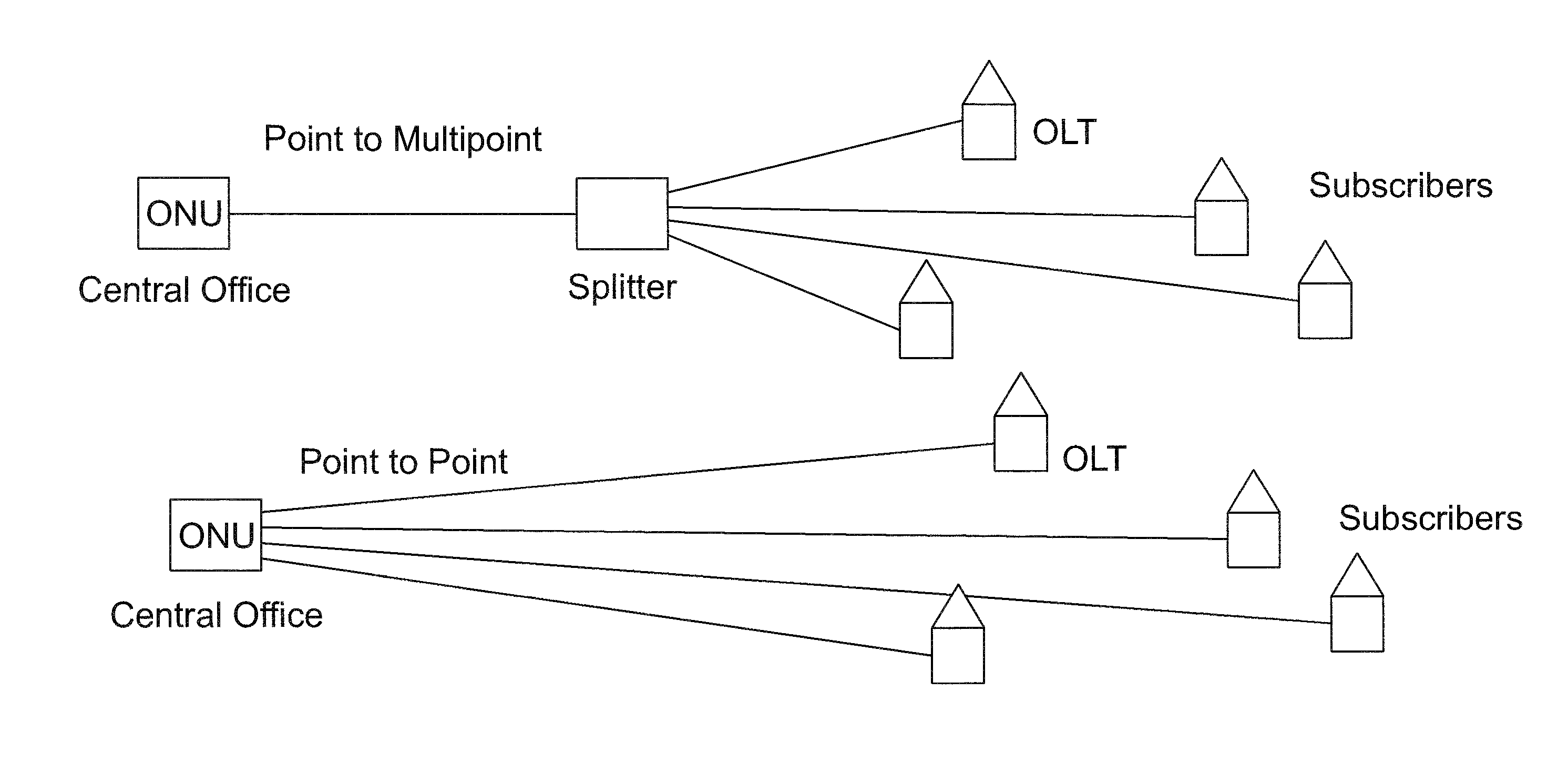
[0001]The present invention relates to optical networks, especially branched optical fiber networks in a telecommunications system, to methods of operating such networks and devices and software for use with such networks. In particular, the present invention relates to devices and methods for optical measurements in passive point-to-point and point-to-multipoint networks (like PON networks with splitters).TECHNICAL BACKGROUND[0002]FIG. 1 shows schematically networks between a central office and subscribers such as a point-to point optical telecommunications network and a point to multipoint optical telecommunications network having a splitter and branch fibers. A passive optical network (PON) is a point-to-multipoint network architecture in which unpowered optical splitters are used to enable a single optical fiber to serve multiple premises, typically 32-128. A PON consists of an Optical Line Terminal (OLT and a number of Optical Network Units (ONUs).[0003]Network operators have a...

Claims


Application Information

Patent Timeline
IPC IPC(8): H04B10/08G02B6/26H04B10/071
CPCH04B10/071G01M11/3136
Inventor DAEMS, DANIEL
Owner COMMSCOPE CONNECTIVITY BELGIUM BVBA
Learn More