
Unintended Motion Control For Manually Directed Multi-Channel Electronic Pipettor

a multi-channel electronic pipettor and manual motion control technology, which is applied in the direction of sampling, laboratory glassware, instruments, etc., can solve the problems of unusable force and unsuitable under normal operating conditions, and achieve the effect of substantial lateral stability

Active Publication Date: 2011-11-03
INTEGRA BIOSCI CORP
View PDF3 Cites 38 Cited by
  • Summary
  • Abstract
  • Description
  • Claims
  • Application Information

AI Technical Summary

Benefits of technology

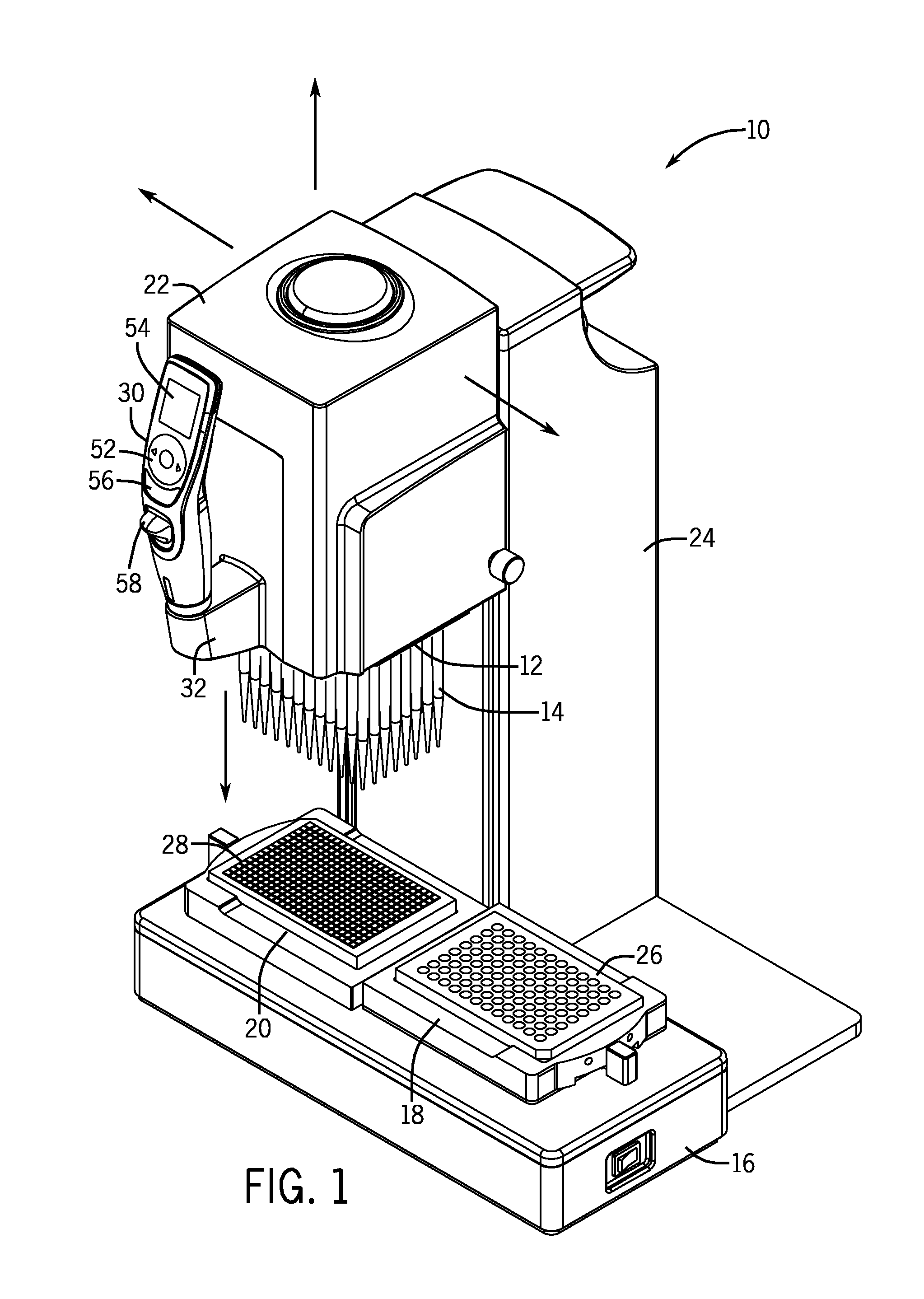
[0009]Another aspect of the invention recognizes the desirability of keeping the user's hands free of the motor driven pipetting head during the tip attachment process in order to protect the user from injury. In this regard, the preferred embodiment of the invention is implemented in a system having a multi-channel pipetting head with 96-tip fittings. The multi-channel pipetting head is preferably carried in a carriage mounted to a tower. A deck is located below the pipetting head and is adapted to hold at least one multi-wellplate or reagent reservoir, as well as a tip tray full of an array of 96-pipette tips. A control handle, preferably mounted to the carriage for the pipetting head, is held in the hand that the user normally uses for pipetting. An electronic control system that moves the pipetting head relative to the deck in accordance with the direction and amount of force applied to the control handle, as described in accordance with the above mentioned co-pending patent applications. In accordance with this aspect of the present invention, the system includes a tip attach button that must be activated in order to continue lowering the pipetting head to attach the disposable pipette tips to the tip fittings on the pipetting head. As mentioned, the required tip insertion force may be significant. The tip attach button is preferably located on the top of the carriage for the pipetting head, and requires activation by the user's other hand. In this manner, the user's hands are occupied when the vertical drive mechanism lowers the pipetting head to insert the tip fittings into the pipette tip collar, thereby preventing the opportunity that one of the user's hands be located in an unsafe location when the tips are being attached. In accordance with the invention, it is not necessary for the tip attach button to be located on the top of the carriage. The tip attach button may be located on another part of the system, or may be located on the laboratory bench top.
[0011]Preferably, the tip fittings and the pipette tips are the same or similar to that described in U.S. Pat. Nos. 7,662,343 and 7,662,344 both entitled “Locking Pipette Tip and Mounting Shaft” by Greg Mathus, Terrence Kelly and Rich Cote, both assigned to the Assignee of the present application and incorporated herein by reference. The tip fittings described in these patents provide substantial lateral stability for the attached pipette tips. This enables the user to simultaneously touch off the mounted pipette tips, e.g. 96-pipette tips, and remain confident that the tips will remain properly attached and aligned on the tip fittings.

Problems solved by technology

However, such force is not necessary and not desirable under normal operating conditions other than for tip attachment.

Method used


Image

  • Unintended Motion Control For Manually Directed Multi-Channel Electronic Pipettor
  • Unintended Motion Control For Manually Directed Multi-Channel Electronic Pipettor
  • Unintended Motion Control For Manually Directed Multi-Channel Electronic Pipettor

Examples


Embodiment Construction

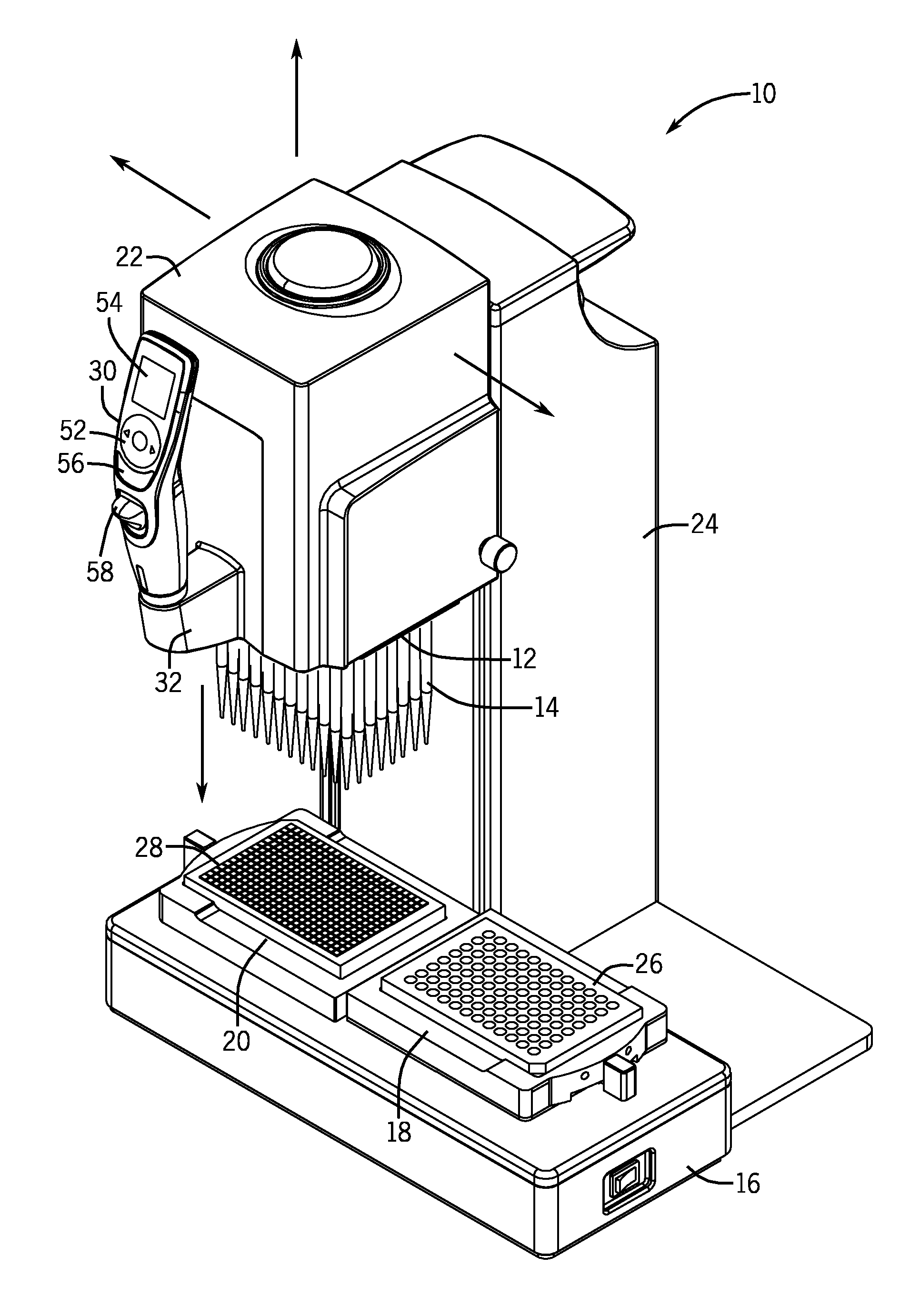
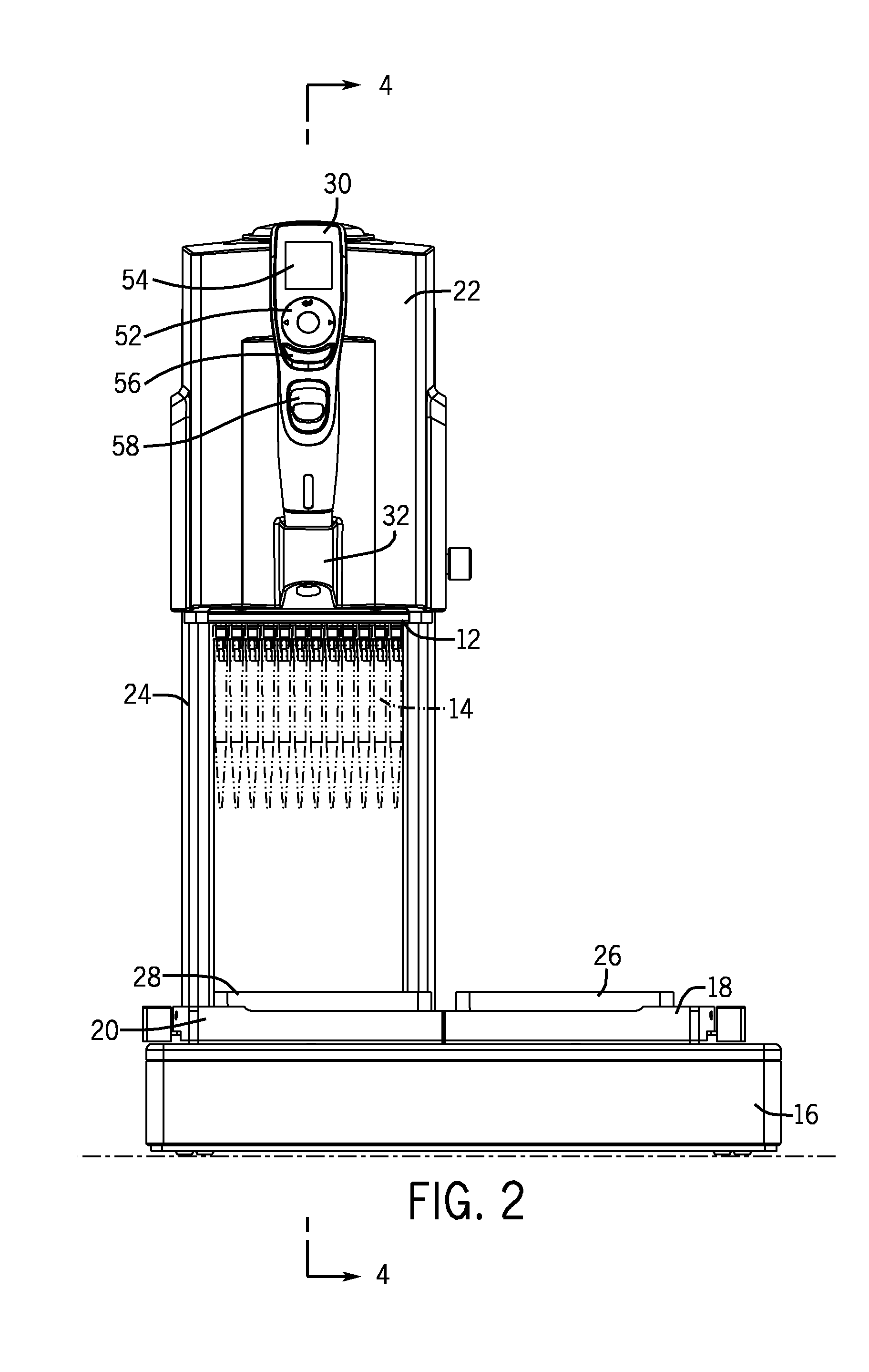
[0031]An embodiment of a manually directed, multi-channel electronic pipetting system 10 as described in the above incorporated patent applications is shown in FIGS. 1-3. Referring to FIGS. 1-3, the manually directed, multi-channel electronic pipetting system 10 includes a multi-channel pipetting head 12 having a plurality of pipetting channels arranged in a two dimensional array of rows and columns. Normally, the pipetting head 12 will include an array of 96-tip fittings. An array of pipette tips 14 are attached to the multi-channel pipetting head 12. The manually directed, multi-channel electronic pipetting system 10 includes a flat deck 16 supporting a right nesting receptacle 18 and a left nesting receptacle 20. The nesting receptacles 18, 20 are designed to hold multi well-plates, reagent reservoirs or tip racks in a known location on the deck 16.

[0032]The pipetting head 12 is removably mounted to a carriage 22 which in turn is mounted to a tower 24. A pipetting motor located w...


PUM


Abstract

A manually directed, electronic multi-channel pipettor uses servo controlled motors to drive a carriage and pipetting head in response to a user's manipulation of a control handle. The pipetting head include an array of tip fittings, e.g. 96. The system includes a check processor to avoid unintended motion in case of system faults or crashes. The system requires substantial force to attach the array of tips, and therefore includes controls that require both of the user's hands be occupied during the tip attachment process.

Description

FIELD OF THE INVENTION[0001]The invention relates to a manually-directed, electronic pipetting system having a multi-channel pipetting head with a plurality of pipetting channels, e.g., 96-channels, arranged in an array of rows and columns. In particular, the invention pertains to protecting against unintended motion, e.g. when attaching disposable pipette tips onto fittings of the pipetting head or otherwise.BACKGROUND OF THE INVENTION[0002]Multi well-plates, also known as microtiter plates or micro well-plates, are standard products in clinical and research laboratories. A multi-well plate is a flat plate with multiple wells used as individual test tubes. The most common multi-well plates include 96-wells or 384-wells arranged in a rectangular matrix. ANSI has set standardized dimensions and SBS footprints for well-plates. For example, a 96-well plate has 8 rows and 12 columns of wells centered 9 mm centerline-to-centerline. A typical 384-well plate includes 16 rows and 24 columns...

Claims


Application Information

Patent Timeline
IPC IPC(8): B01L3/02
CPCB01L3/0227B01L3/0234B01L3/0237G01N35/1074B01L2300/027B01L2300/0829B01L2400/0478B01L2200/087
Inventor WARHURST, JULIANCOTE, RICHARD
Owner INTEGRA BIOSCI CORP
Learn More