Agricultural Combine And Draper Header

a technology of draper headers and combiners, which is applied in the field of agricultural combiners with feederhouses and draper headers, can solve the problems of serious damage, weight balance on one side, and the dislodge of draper headers from feederhouses

Active Publication Date: 2011-11-03
DEERE & CO
View PDF15 Cites 34 Cited by
  • Summary
  • Abstract
  • Description
  • Claims
  • Application Information

AI Technical Summary

Benefits of technology

[0023]An electronic controller is coupled to the means for sensing and the motors driving the conveyor belts, reel, and two reciprocating knives. This electronic controller is programmed to determine whether one of the left and right conveyor belts is becoming overloaded or is slipping based at least upon signals from the means for sensing. The electronic controller is programmed to shut down an auxiliary components (for example the reel, one or both of the reciprocating knives , or the other conveyor in order to prevent the header from becoming unbalanced to the left or to the right (depending upon which conveyor is overloaded) due to accumulation of excess crop on a stopped conveyor belt.

Problems solved by technology

Another problem that can dislodge a draper header from the feederhouse is a weight in balance on one side of the feederhouse versus the other.
Upon occasion, however, it is anticipated that too much crop can accumulate on one side of the header, causing it to roll (i.e. rotate about a longitudinal axis extending in the direction of travel) until one end or the other contacts the ground, at which point there can be serious damage.
If this cut crop material piles too deeply on the stopped conveyor belt, it can overbalance the draper header causing the draper header to tilt downward on the heavier laden side until it lifts off the feederhouse, rams into the ground, or both.
This can cause serious damage to the draper header, and, even if it does not damage the draper header, can delay the farmer from harvesting as he must first manually unload the now-overburdened conveyor belt before he can attempt to started running again.
It is necessary that he first manually unload the conveyor belt, because any attempt to start the conveyor belt with a massive pile of cut crop material can cause the drive roller to slip with respect to the conveyor belt and burn the conveyor belt.
The problem may not be solved, however, merely by stopping the overloaded or slipping conveyor belt.
Eventually this will overbalance the header due to the additional weight building up on the right conveyor belt.
Alternatively, if the additional weight is too great, it will eventually stall the right conveyor belt, causing the right conveyor belt to slip.

Method used


Image

  • Agricultural Combine And Draper Header
  • Agricultural Combine And Draper Header
  • Agricultural Combine And Draper Header

Examples


Embodiment Construction

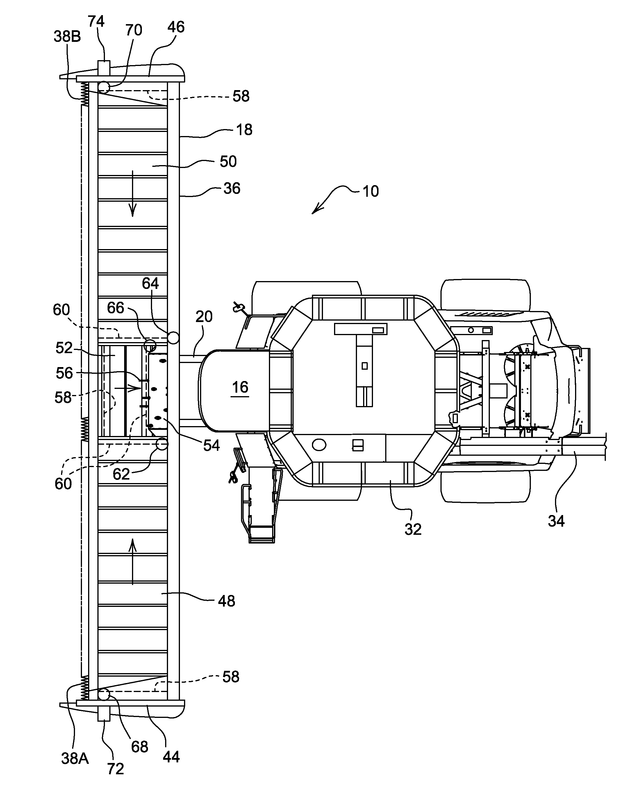
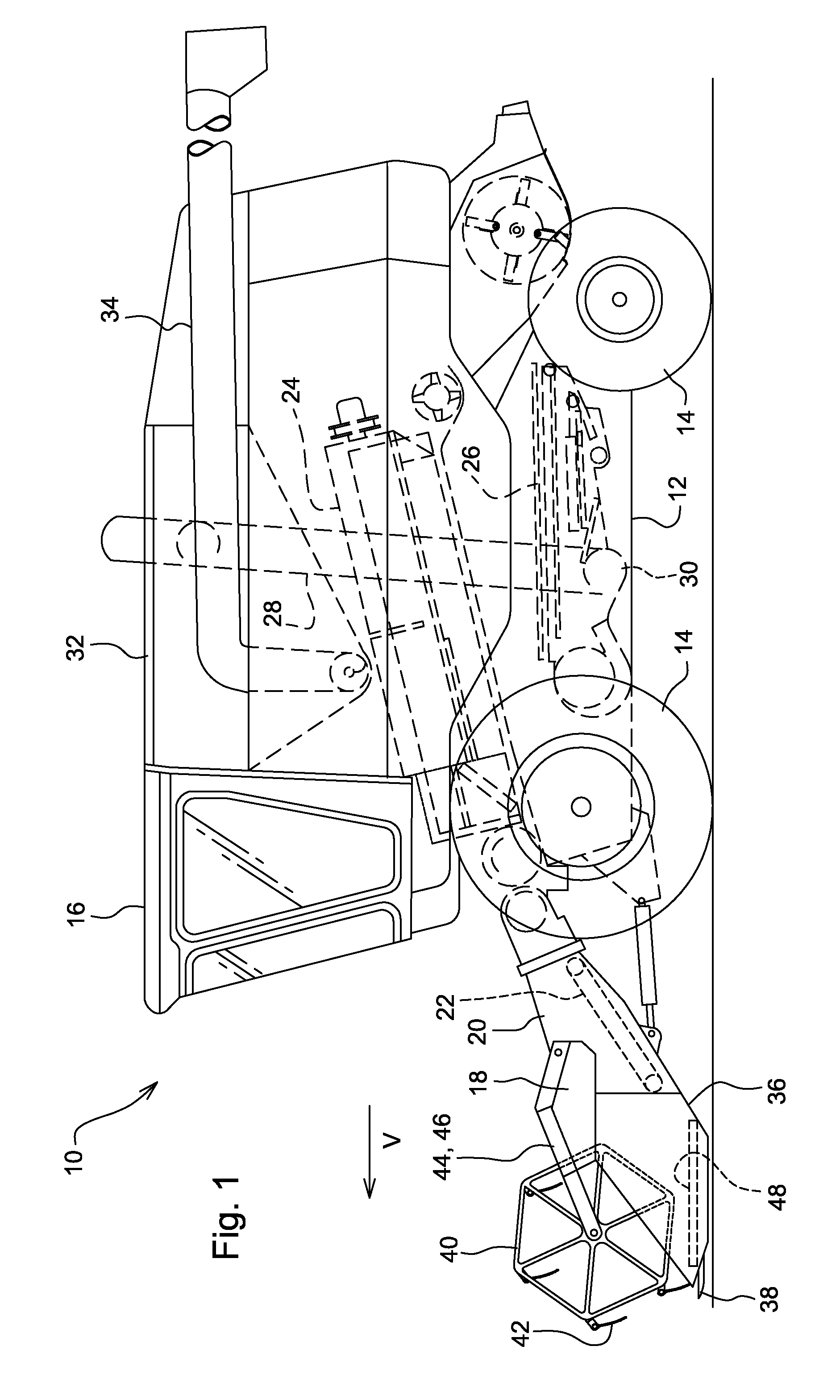
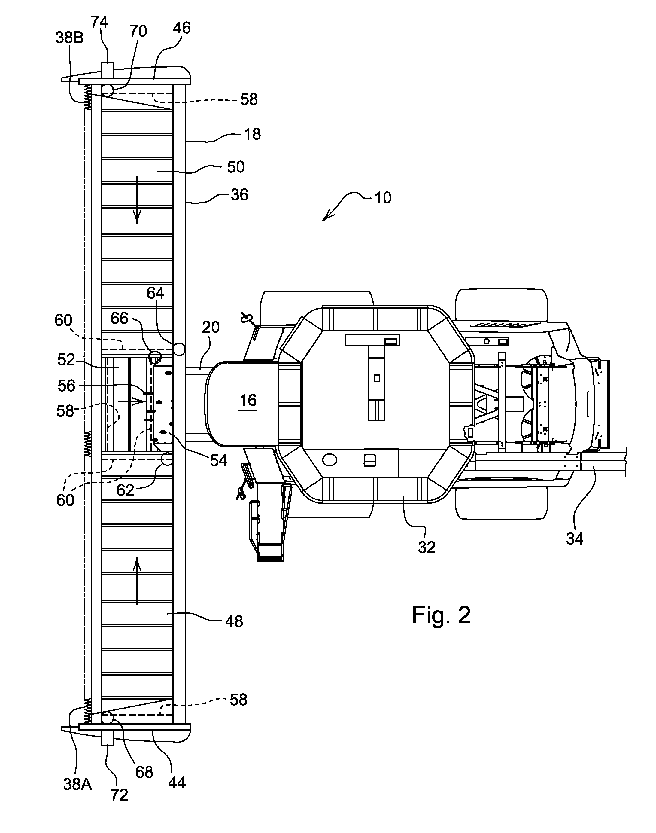
[0029]FIG. 1 shows an agricultural combine 10 with a chassis 12 with wheels 14 that engaged the ground and are mounted on chassis 12. Wheels 14 serve to propel combine 10 in the forward direction “V”, which runs to the left in FIG. 1. The forward direction is the direction the agricultural combine 10 travels when harvesting. The operation of combine 10 is controlled from the operator cab 16. A draper header 18 is supported on feederhouse 20, which has a conveyor 20 disposed therein to carry crop from the draper header 18 to a thresher and separator 24 disposed inside the body of agricultural combine 10. Grain falling from thresher and separator 24 passes into a cleaner 26 which includes a sieve and a chaffer that separate the grain from dust and chaff. Once cleaned in the sieve and chaffer, the clean grain is deposited in an auger conveyor 30 located at the bottom of agricultural combine 10. Auger conveyor 30 carries the clean grain to the right side of agricultural combine 10 and i...


PUM


Abstract

An agricultural combine with draper header includes left and right conveyors, and a microprocessor-based controller coupled to the conveyors to determine whether one of the conveyors is overloaded or slipping.

Description

FIELD OF THE INVENTION[0001]The invention relates to agricultural combines with feederhouses and draper headers configured to be supported on said feederhouses.BACKGROUND OF THE INVENTION[0002]Agricultural combines are large machines that harvest, thresh, separate and clean agricultural crops that bear grain. The clean grain obtained is stored in a grain tank arranged on the combine. The threshed straw is generally chopped and spread out on the field across the width of the chopping mechanism.[0003]In one common arrangement, the cut crop material from which the gain is extracted is gathered by a laterally extending “header” that rest so on a feederhouse which extends forward from the agricultural combine in the direction of travel of the combine as it travels through the field harvesting crop. The header extends transversely with respect to the direction of travel and can be as much as 40 or 50 feet wide. Typically, headers are supported on a feederhouse that has a width of 4-6 feet...

Claims


Application Information

Patent Timeline
Patent Type & Authority Applications(United States)
IPC IPC(8): A01D41/127A01D41/06G08B5/22G06F7/00
CPCA01D57/20A01D41/142
Inventor IMHOF, CRYSTALPURYK, CORWIN MARCUS RAYMOND
Owner DEERE & CO
Why Eureka
Try Eureka