Multistage liquefied gas expander with variable geometry hydraulic stages

a technology of hydraulic stages and liquefied gas, which is applied in the direction of electric generator control, fluid couplings, lighting and heating apparatus, etc., can solve the problems of commercial unattractiveness and technology not being commercially available, and achieve the effect of reducing temperature, thermodynamic internal energy, and temperature reduction

Active Publication Date: 2011-11-10
ELLIOTT CO
View PDF6 Cites 1 Cited by
  • Summary
  • Abstract
  • Description
  • Claims
  • Application Information

AI Technical Summary

Benefits of technology

[0010]The purpose of liquid expanders in gas liquefaction processes is to further reduce the temperature of the liquefied gas beyond the typically very low cryogenic liquefaction temperature without going through the Carnot refrigeration process. The cryogenic liquid expander directly extracts the heat energy from the liquefied gas by expanding the liquid from a high pressure level to a low pressure level, converting the static pressure energy into kinetic fluid energy and further into mechanical torque and electrical energy where it is ultimately removed from the system. By extracting work in the form of electrical energy from the cryogenic fluid, the thermodynamic internal energy, the enthalpy, is reduced and with it the temperature is reduced.

Problems solved by technology

This process yielded the desired result, but unfortunately had a high energy consumption that made it commercially unattractive.
The engineering challenges associated with the design of engines operating at cryogenic temperatures coupled with the stringent safety and hazard rules for explosive fluids prevented the technology from being commercially available prior to this installation.

Method used


Image

  • Multistage liquefied gas expander with variable geometry hydraulic stages
  • Multistage liquefied gas expander with variable geometry hydraulic stages
  • Multistage liquefied gas expander with variable geometry hydraulic stages

Examples


Embodiment Construction

[0019]Embodiments are directed to a multistage expander, operating in single phase or in two-phase, having two or more hydraulic stages with different physical geometries. In an embodiment, a first hydraulic stage uses nozzle vanes machined with a first geometry, while a second hydraulic stage uses nozzle vanes machined with a second geometry. Different nozzle vanes are combined within the expander to tune the performance of the expander as the optimal operating conditions change. Expanders disclosed can be used with liquefied natural gas (LNG) and cryogenic fluids.

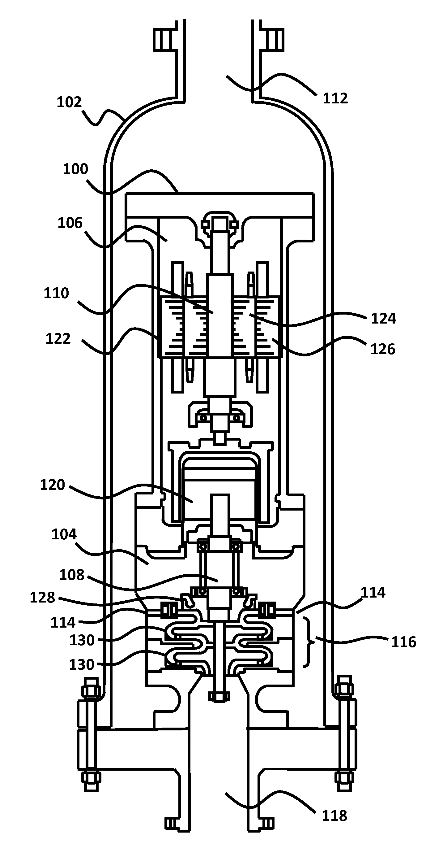
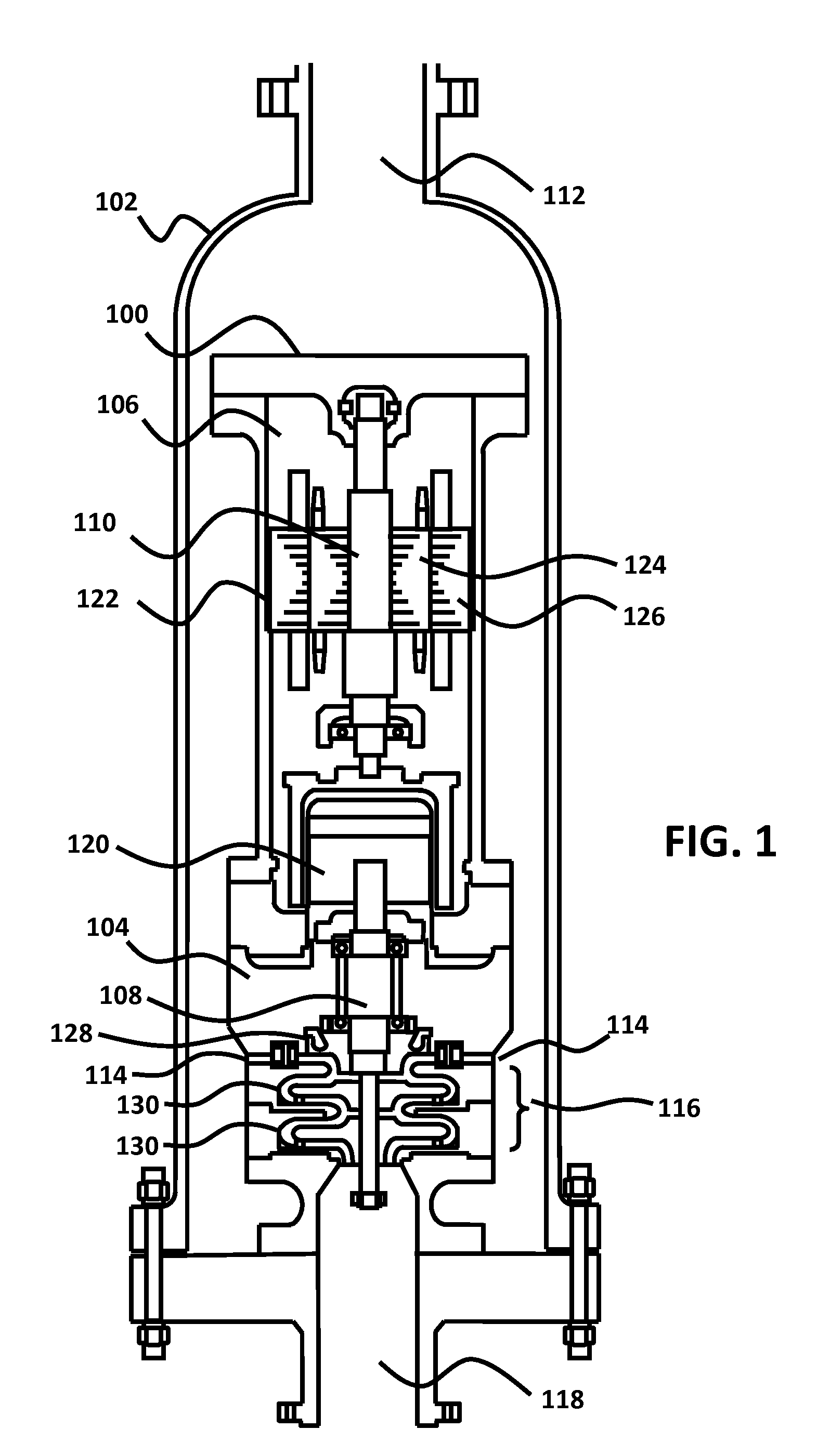
[0020]FIG. 1 illustrates an expander 100 inside a vessel 102, which is slightly larger than the expander 100. The expander 100 consists of a hydraulics section 104 and a generator section 106 mounted with a vertical rotational axis. The hydraulics section 104 and the generator section 106 can be mounted on the same shaft, or they can be mounted on separate shafts. In the expander 100 the hydraulics section 104 is mounted ...


PUM


Abstract

Embodiments are directed to an expander having two or more hydraulic stages with different physical geometries. In an embodiment, a first hydraulic stage uses nozzle vanes machined with a first geometry, while a second hydraulic stage uses nozzle vanes machined with a second geometry. Different nozzle vanes can be combined to tune the performance of the expander as the optimal operating conditions change. In yet another embodiment, an expander is equipped with a generator having a double wound stator with two sets of parallel windings. For high operating loads greater than a threshold, a first set of windings operates while a second set of windings, operating at a lower frequency, is disconnected. For operating loads that are less than the threshold, the first set of windings is disconnected and the second set of windings operates, enabling the generator to continue to operate close to 100% load for less expander power.

Description

CROSS-REFERENCES TO RELATED APPLICATIONS[0001]This application claims priority to U.S. Provisional Application No. 61 / 343,964, filed May 5, 2010, which is incorporated by reference in its entirety to be considered part of this specification.BRIEF DESCRIPTION OF THE INVENTION[0002]Embodiments are directed to an expander having two or more hydraulic stages with different physical geometries. In an embodiment, a first hydraulic stage uses nozzle vanes machined with a first geometry, while a second hydraulic stage uses nozzle vanes machined with a second geometry. Different nozzle vanes can be combined in an expander to tune the performance of the expander as the optimal operating conditions change. In yet another embodiment, an expander is equipped with a generator having a double wound stator with two sets of parallel windings. For operating loads greater than a threshold, a first set of windings operates and is connected to the power grid while a second set of windings is disconnecte...

Claims


Application Information

Patent Timeline
Patent Type & Authority Applications(United States)
IPC IPC(8): F15B13/00
CPCF01D15/005F03B13/00F05B2220/602F25J1/0022F05D2220/62F25J1/0257F25J2240/30Y02B10/50F25J1/0042
Inventor CORDS, MICHAEL LEE
Owner ELLIOTT CO
Why Eureka
Try Eureka