
Low-loss cryostat configuration

a cryostat and low-loss technology, applied in the field of cryostat configuration, can solve the problems of reducing the interval between helium refills, achieving the effect of superconducting short-circuited operation, and producing high magnetic field in short-circuited

Inactive Publication Date: 2011-11-10
BRUKER BIOSPIN
View PDF7 Cites 5 Cited by
  • Summary
  • Abstract
  • Description
  • Claims
  • Application Information

AI Technical Summary

Benefits of technology

[0030]It is advantageous if, in the embodiments stated above, the pressure regulating device sets the pressure in the fur...

Problems solved by technology

The superconducting magnet coils only require energy during the charging phase and produce a high magnetic field in short-circuited operation for a long time after the power supply has been disconnected.
This can only be achieved in superconducting short-circuited operation.
One major disadvantage of this configuration is that the supercooled helium in the inner tank is under vacuum so that the electrical supply cables, especially those for charging the superconducting magnet coil, have to be routed through the cold vacuum system.
This gives rise to sealing problems and also insulation problems due to the heat input into the cold vacuum reservoir through the supply cables brought in from an environment at room temperature and under normal pressure, which necessarily results in much reduced intervals between helium refills.
A further disadvantage is that no means are provided to lower the helium consumption required to operate this equipment, with the result that both enormous operating costs are incurred and only relatively short intervals between liquid helium refills are achieved, except in cases where it is in any event necessary to constantly fill the equipment with fresh helium during operation.

Method used


Image

  • Low-loss cryostat configuration
  • Low-loss cryostat configuration
  • Low-loss cryostat configuration

Examples


Embodiment Construction

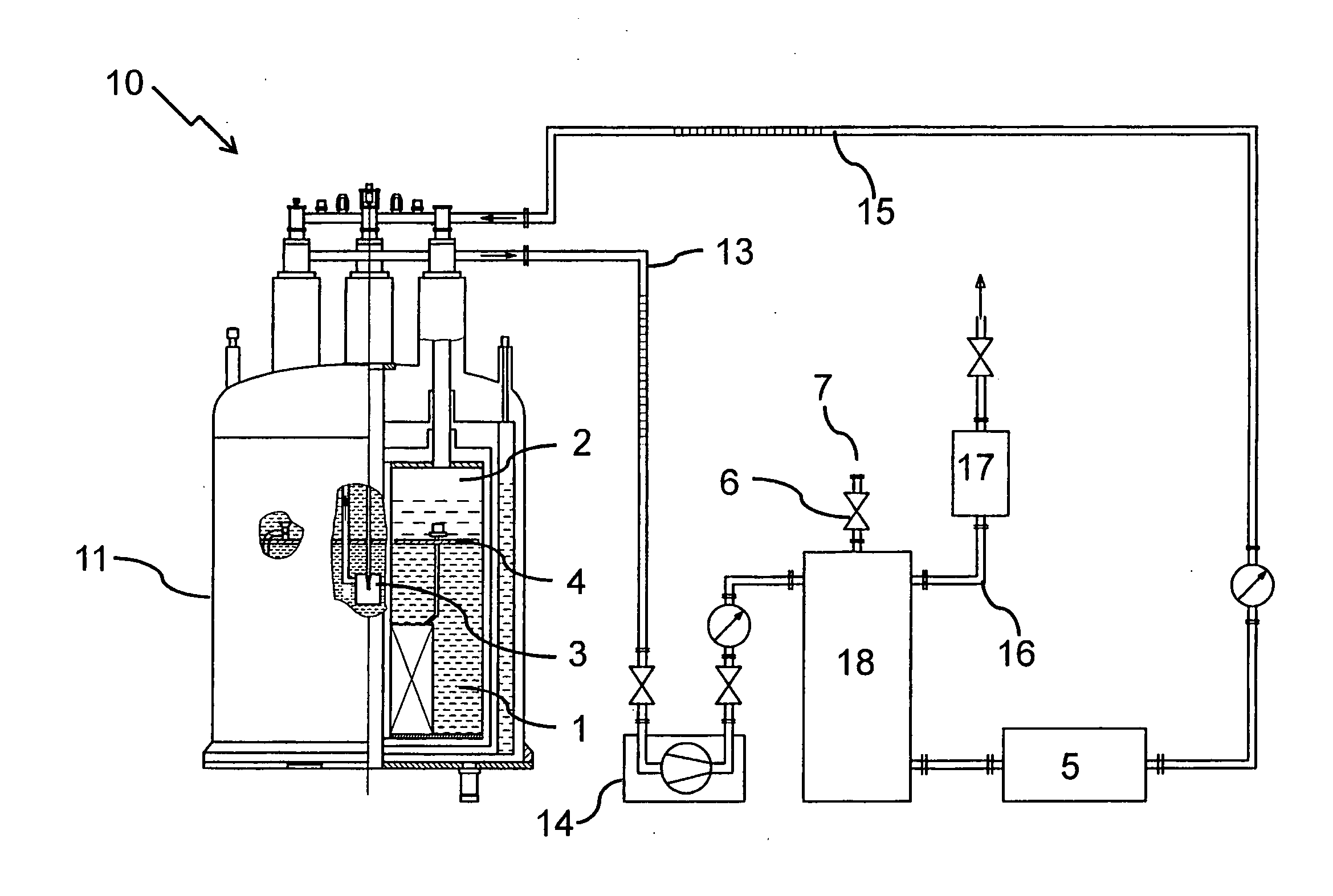
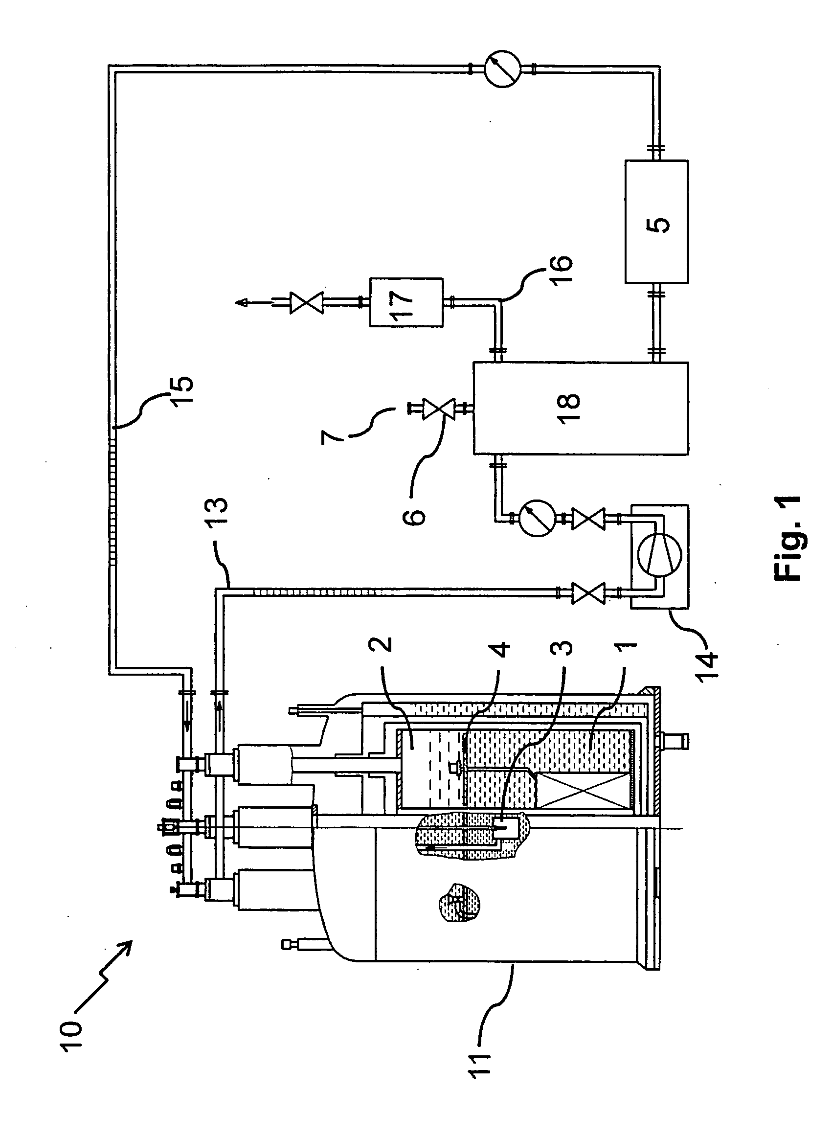
[0048]FIG. 1 shows an embodiment of an inventive cryostat configuration 10 with one cryostat 11 with supercooled helium. The cryostat 11 consists of a first chamber 1 with supercooled helium (temperature 2 with liquid helium (temperature approx. 4.2 K), that are separated by a thermally insulating barrier 4. In the first chamber 1, a Joule-Thomson valve 3 is disposed through which the helium can expand from the further chamber 2 into the pump-off pipe 13, thus supercooling the first chamber 1. The helium is pumped off from the pump-off pipe 13 by a pump 14 and led to a cryogen pipe 15. In the embodiment depicted, the latter comprises a buffer vessel 18 to provide to the helium an additional volume that can serve as a pressure reserve and / or backflow reserve. A relief valve 6 with a bursting disk 7 prevents an excessive pressure in the cryogen pipe 15 if the pressure regulating device 17 of the branch-off device 16 fails or if the pressure cannot be kept constant for any other reason...


PUM


Abstract

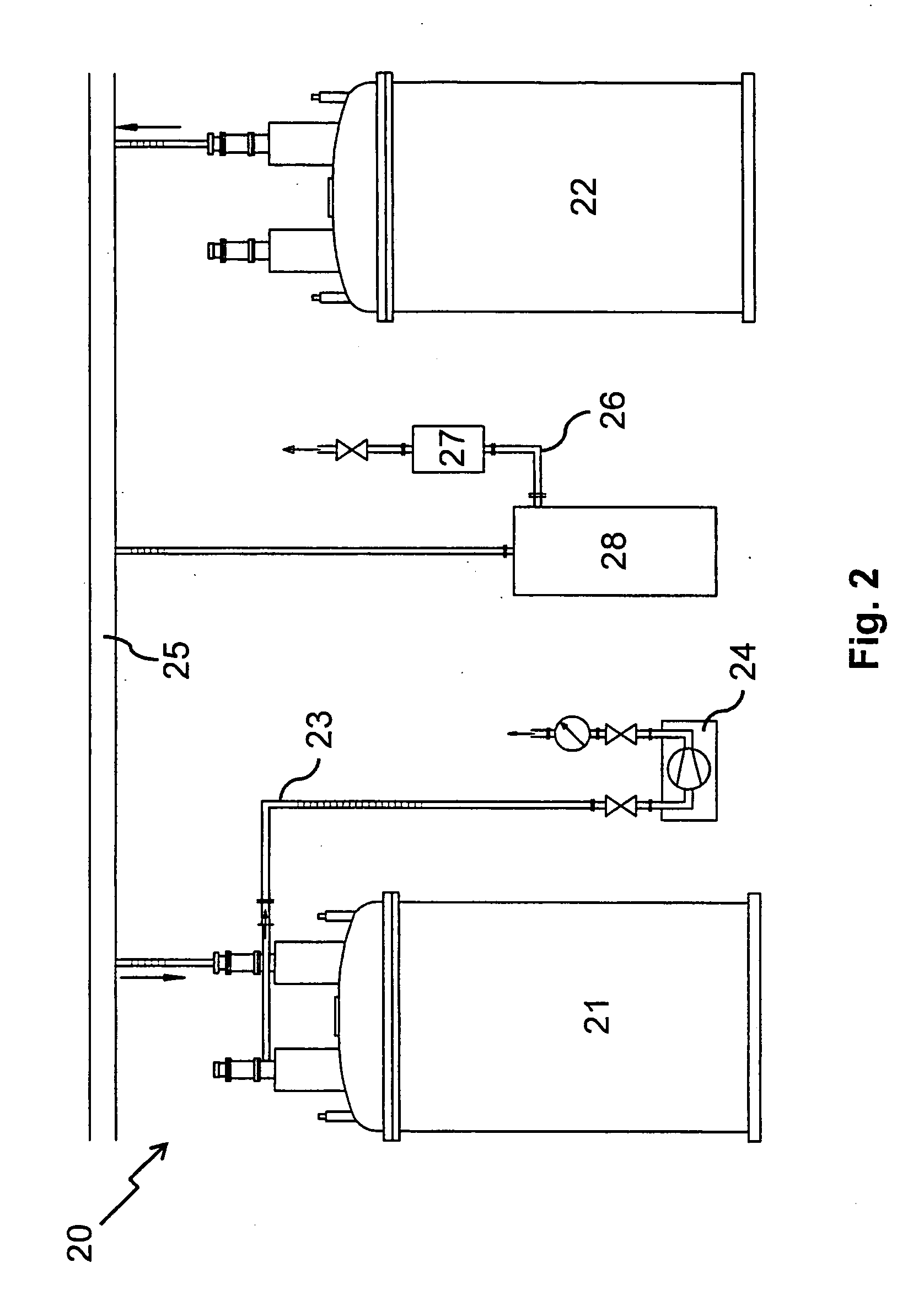
A cryostat configuration (10), with at least one cryostat (11), which has at least one first chamber (1) with supercooled liquid helium having a temperature of less than 4 K and at least one further chamber (2), which contains liquid helium having a temperature of approximately 4.2 K, a Joule-Thomson valve (3) being disposed in the first chamber, wherein the first chamber is separated from the further chamber by a thermally insulating barrier (4), wherein helium from the first or the further chamber expands through the Joule-Thomson valve into a pump-off pipe (13), which is in thermal contact with the helium of the first chamber and supercools the latter, and wherein the pump-off pipe is directly or indirectly in thermal contact with the further chamber during its further progression and is then connected to the inlet of a pump (14), is characterized in that the outlet of the pump and / or an outlet for evaporating helium of at least one of the cryostats is fluidically connected to the further chamber through a cryogen pipe (15), and that the cryogen pipe has a branch-off device (16), which returns a partial current of the helium located in the cryogen pipe into the further chamber. In this way, the helium consumption and therefore the operating costs are reduced while the pressure in the first chamber remains constant.

Description

[0001]This application claims Paris Convention priority of DE 10 2010 028 750.4 filed May 07, 2010 the complete disclosure of which is hereby incorporated by reference.BACKGROUND OF THE INVENTION[0002]The invention concerns a cryostat configuration, with at least one cryostat, which has at least one first chamber with supercooled liquid helium having a temperature of less than 4 K and at least one further chamber, which contains liquid helium at essentially atmospheric pressure having a temperature of approximately 4.2 K, wherein a Joule-Thomson valve is disposed in the first chamber, the first chamber being separated from the further chamber by a thermally insulating barrier, wherein helium from the first or the further chamber expands through the Joule-Thomson valve into a pump-off pipe, which is in thermal contact with the helium of the first chamber and supercools the latter, and wherein the pump-off pipe is directly or indirectly in thermal contact with the further chamber duri...

Claims


Application Information

Patent Timeline
IPC IPC(8): F25B19/00
CPCH01F6/04F25D19/00F17C13/006F25J1/02
Inventor STROBEL, MARCOROTH, GERHARD
Owner BRUKER BIOSPIN
Learn More