Hydraulic fracture height growth control

a technology of hydraulic fracture and height growth, applied in fluid removal, chemistry apparatus and processes, borehole/well accessories, etc., can solve the problems of vertical fracture growth, fracture height control, barrier rocks will also crack, etc., and achieve the effect of reducing the viscosity, reducing the viscosity and reducing the viscosity

Inactive Publication Date: 2011-11-10
SCHLUMBERGER TECH CORP
View PDF5 Cites 27 Cited by
  • Summary
  • Abstract
  • Description
  • Claims
  • Application Information

AI Technical Summary

Problems solved by technology

Fracture height control is a common challenge faced by operators designing hydraulic fracture treatments, particularly in low permeability reservoirs.
However, when the surrounding formation is too weak to withstand the pressure required to propagate the fracture, the barrier rocks will also crack and the vertical fracture growth will continue.
This process results in poor fracture efficiency, since some of the fracture area lies outside the productive zone.
Fracture growth downwards may also lead to water breakthrough, if there is a water zone below the reservoir.
Water breakthrough limits oil production as well as increases the operational costs in order to separate and dispose of the water.
Fracture growth in the upward direction is undesirable as well, since there might be a gas cap and eventually breakthrough into this zone might stimulate gas production.
This could also result in the reduced ultimate recovery.
Even if there is no gas cap or water zone, undesired fracture growth is wasteful.

Method used


Image

  • Hydraulic fracture height growth control
  • Hydraulic fracture height growth control
  • Hydraulic fracture height growth control

Examples


example 1

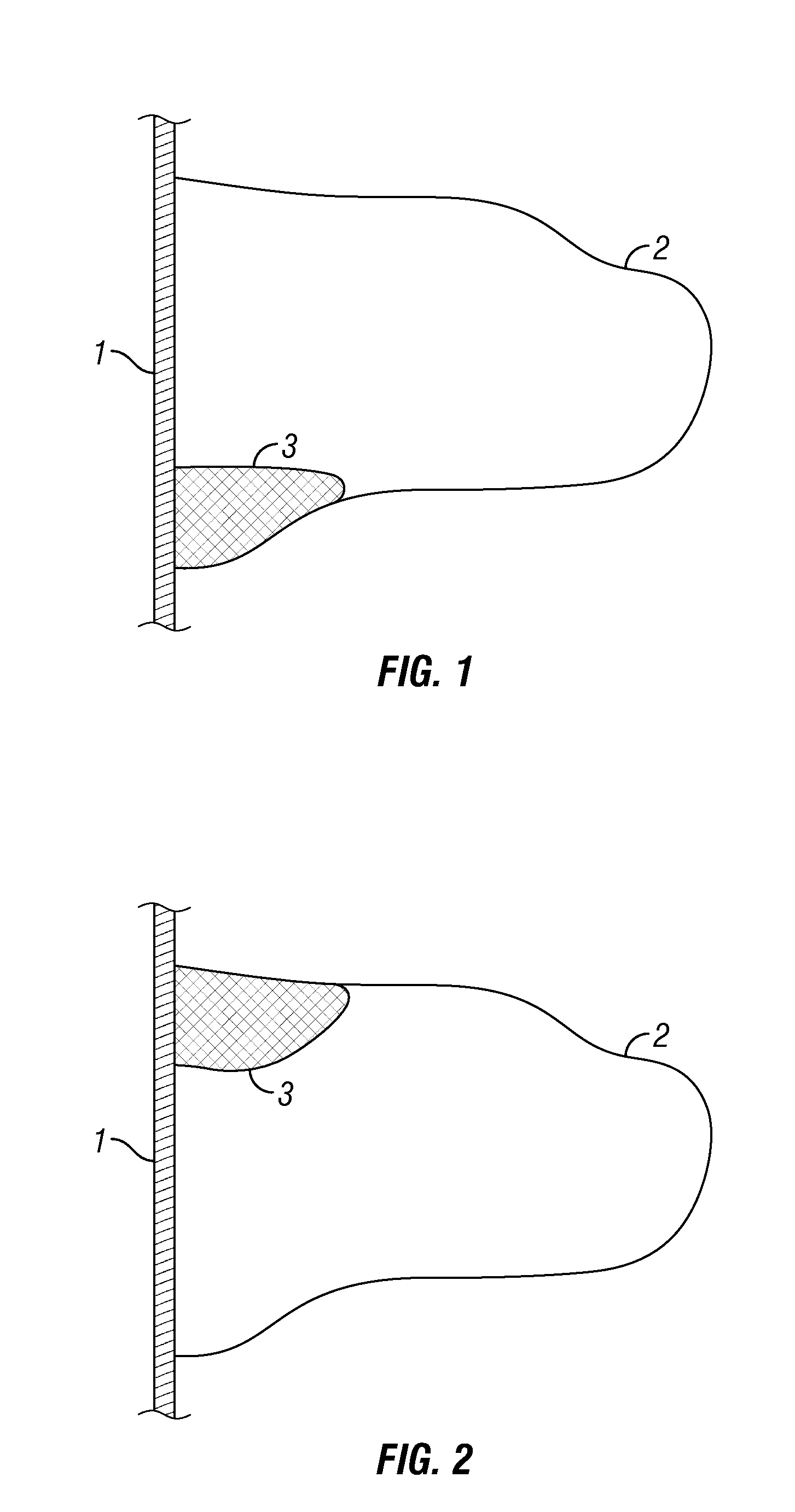
[0048]This example demonstrates how the method of the Invention performs under typical field conditions. Table 1 shows the pumping schedule and FIG. 1 demonstrates the particle concentration distribution after the end of stage 4, calculated (as in all the examples) using a pseudo 3D fracturing simulator (fracture design, prediction, evaluation and treatment-monitoring program) commercially available under the trade designation FracCADE™ from Schlumberger Technology Corporation, Sugar Land, Tex., U.S.A. The density of the barrier particles (called sand in this and the other examples) was equal to 3600 kg / m3 and the particle mean diameter was 0.589 mm (20 / 40 mesh sand). The “highly-viscous” fluid parameters were as follows: the power-law exponent was n=0.59 and the consistency was K=0.383 Pasn; the density was that of water, and the apparent viscosity was μ=28.1 cP at a shear rate equal to 170 s−1. (The fluid modeled contains 3.6 kg / m3 bromate-crosslinked guar.) The “low-viscosity” fl...

example 2

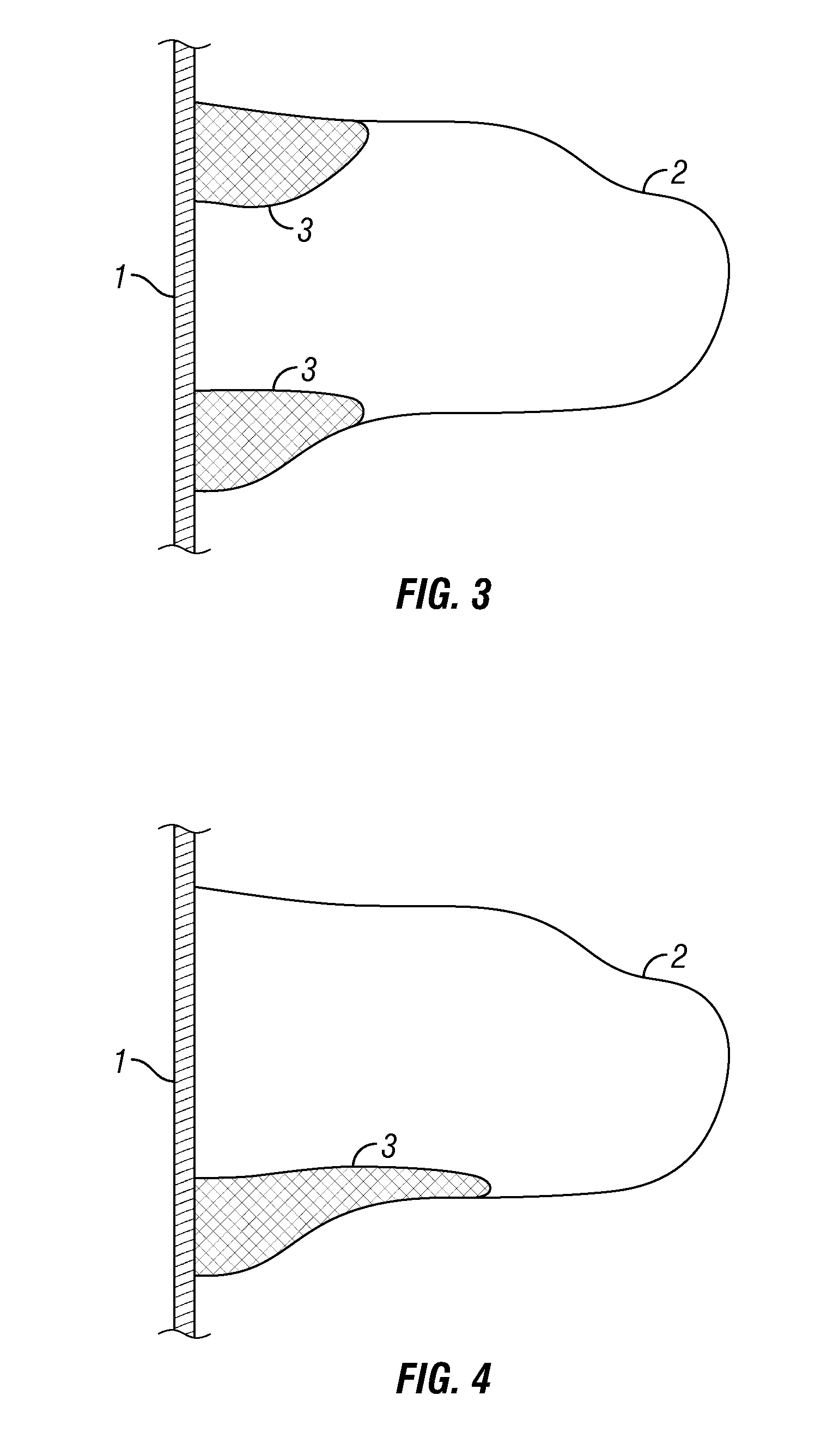
[0050]The next example illustrates the placement of a barrier stretched along the bottom edge of the fracture. In order to provide an elongated barrier, an auxiliary stage was introduced between pumping the barrier particle slug (Stage 2) and injecting the low-viscosity fluid (Stage 4 in this example). At this point (Stage 3) a small portion of clean cross-linked gel was introduced. The extended job design is presented in Table 2.

TABLE 2Treatment schedule for Example 2PumpFluidPar-Par-Slurryrate,Vol-ticleticleVol-Pumpm3 / ume,Par-Conc.,Mass,ume,Time,StageminFluidm3ticleskg / m3kgm3min16.36Low-80—008012.6visc26.36High-10Sand958.61958612.72.0visc36.36High-20—00203.1visc46.36Low-30—00304.7visc56.36High-100—0010015.7visc

[0051]The particle concentration distribution calculated for this job design is shown in FIG. 8. It can be seen that the small stage of clean viscous fluid pushed a portion of the barrier slug farther into the fracture. This job design was optimized for this effect by runnin...

example 3

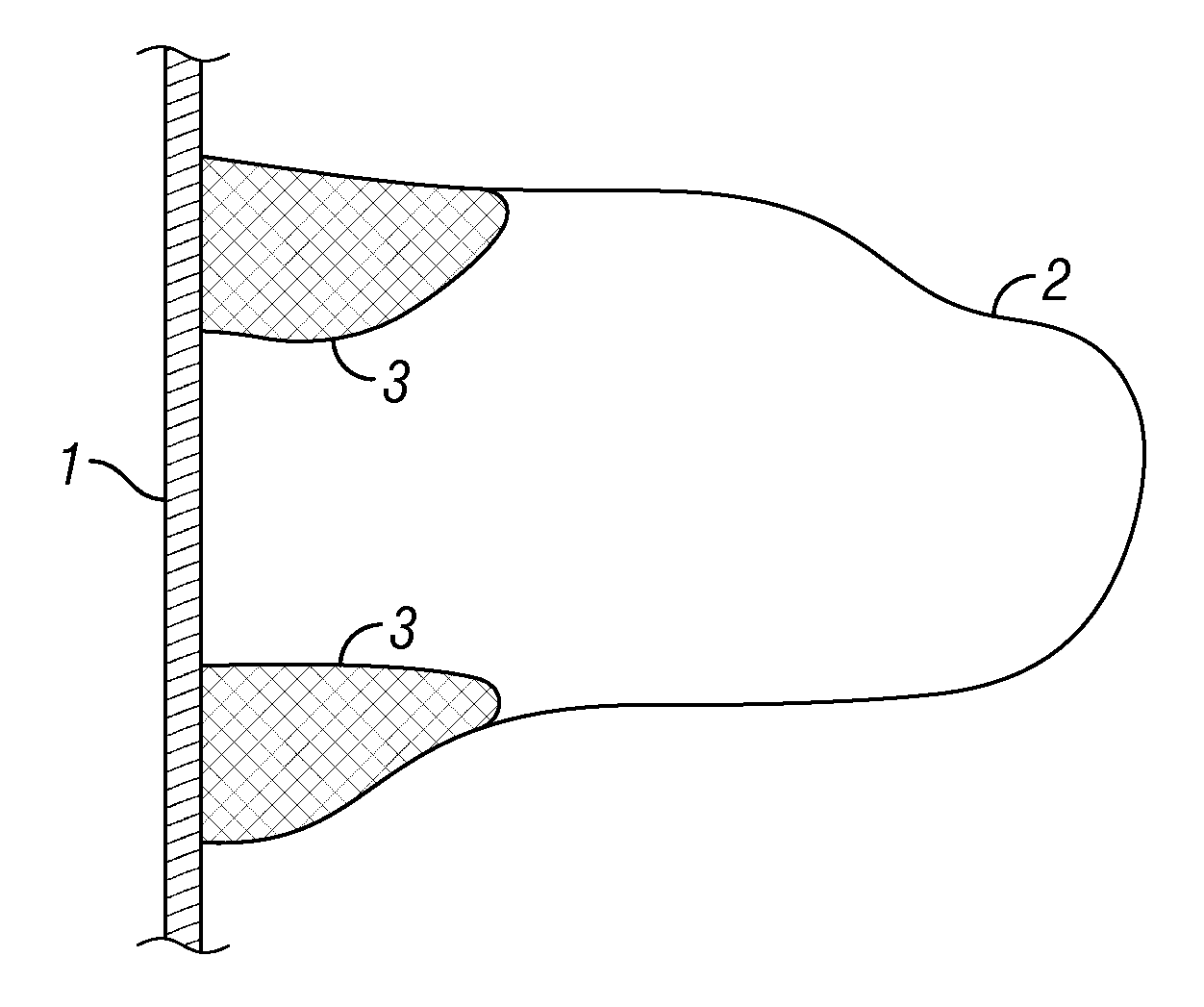
[0052]The next example illustrates the effect of the rheology of the fluid injected before the slug on the final pattern inside the fracture. In this case, the pad fluid used was a highly-viscous cross-linked gel. As a result, two barriers were placed, one at the bottom and one at the top of the fracture. The lower-viscosity fluid fingered into the higher-viscosity fluid according to the Saffman-Taylor instability and cut the barrier particle slug into uneven parts; the larger portion was displaced and then settled towards the bottom and the smaller portion was pushed towards the top. The particles used in this simulation had a mean diameter equal to 0.661 mm and a density of 2540 kg / m3. The results calculated for the particle concentration distribution are summarized in FIG. 9, and the pumping schedule is presented in Table 3.

TABLE 3Treatment schedule for Example 3PumpFluidPar-Par-Slurryrate,Vol-ticleticleVol-Pumpm3 / ume,Par-Conc.,Mass,ume,Time,StageminFluidm3ticleskg / m3kgm3min16.36...


PUM


Abstract

A method is given for creating a fracture, in a subterranean formation, that has a fluid flow barrier at the top, at the bottom, or at both the top and the bottom. The method is applied before or during a conventional hydraulic fracturing treatment and is used to limit undesired vertical growth of a fracture out of the productive zone. A lower-viscosity pad fluid is used to initiate the fracture; a higher-viscosity fluid containing barrier particles is then injected; a lower-viscosity particle-free fluid is then injected to promote settling (or rising) of the barrier particles and to finger through the slug of barrier particles and cut it into an upper and lower portion. If the barrier is to be at the bottom of the fracture, the barrier particles are denser than the fluids; if the barrier is to be at the top of the fracture, the barrier particles are less dense than the fluids. Optionally, between the barrier transport stage and the subsequent lower-viscosity stage, there may be a stage of a higher viscosity particle-free fluid that pushes the barrier particles farther into the fracture. To provide both upper and lower particles in one treatment, the pad stage may be of higher-viscosity, or the barrier particles may include particles less dense than, and more dense than, the fluid.

Description

BACKGROUND OF THE INVENTION[0001]Fracture height control is a common challenge faced by operators designing hydraulic fracture treatments, particularly in low permeability reservoirs. Usually when a fracture is initiated in a productive interval, it grows in all directions until it reaches an interface, for example with upper and lower formations in the common case of a vertical fracture in a horizontal reservoir, and encounters a resistance to its growth. Normally, the surrounding rock contacting the productive formation is tougher and less permeable than the reservoir. If natural barriers exist above and below the reservoir, the vertical growth of the fracture will be restrained and the fracture will propagate within the productive zone. This provides an efficient fracture with the entire surface lying inside the reservoir.[0002]However, when the surrounding formation is too weak to withstand the pressure required to propagate the fracture, the barrier rocks will also crack and th...

Claims


Application Information

Patent Timeline
Patent Type & Authority Applications(United States)
IPC IPC(8): E21B43/26
CPCC09K8/62E21B43/26C09K2208/08E21B43/27
Inventor OSIPTSOV, ANDREI ALEXANDROVICHMEDVEDEV, OLEG OLEGOVICHWILLBERG, DEAN
Owner SCHLUMBERGER TECH CORP
Why Eureka
Try Eureka