Solar module connector and method of use

a technology for solar modules and solar panels, applied in the direction of electric connection bases, coupling contact members, coupling device connections, etc., can solve the problems of poor bond between the two components, existing connectors for connecting solar modules susceptible to water infiltration, etc., to improve the protection of the internal electrical components of the connector from the environment, easy-to-assemble, and easy-to-use effects

Inactive Publication Date: 2011-11-10
TE CONNECTIVITY CORP
View PDF2 Cites 12 Cited by
  • Summary
  • Abstract
  • Description
  • Claims
  • Application Information

AI Technical Summary

Benefits of technology

[0005]The present invention provides a robust, readily-assembled solar module connector. Briefly, rather than overmolding a cable to the connector (a typical prior art approach as mentioned above), the connector of the present invention uses one or more interlocking or cooperating components to form a mechanical seal around the cable extending from the connector housing. Compared with existing solar module connectors, the component seal of the present invention provides enhanced protection against water infiltration, and thus better protects the connector's internal electrical components from the environment. Furthermore, the mechanical seal is achieved through compressive forces, thereby obviating the need for overmolding. As an additional benefit, because the seal between the housing and the cable may be formed using components having similar thermal expansion properties, the seal can withstand weather extremes by virtue of the components and cable expanding and contracting together through temperature changes. Additionally, the mechanical interconnection of the components tends to impart ruggedness to the connector, allowing it to handle relatively-high cable tensile loads and relatively-high impact forces. These beneficial features, among others, are provided by the solar module connectors described below.

Problems solved by technology

It has recently been recognized that existing connectors for connecting solar modules are susceptible to water infiltration.
Without being bound by any theory, the inventors hypothesize that this defect is caused by use of thermally incompatible materials during manufacture.
During such an elevated temperature manufacturing process, if the resin or the cable jacket thermally degrades or there is chemical incombatability between materials, the resulting bond between the two components is poor thereby permitting water infiltration.

Method used


Image

  • Solar module connector and method of use
  • Solar module connector and method of use
  • Solar module connector and method of use

Examples


Embodiment Construction

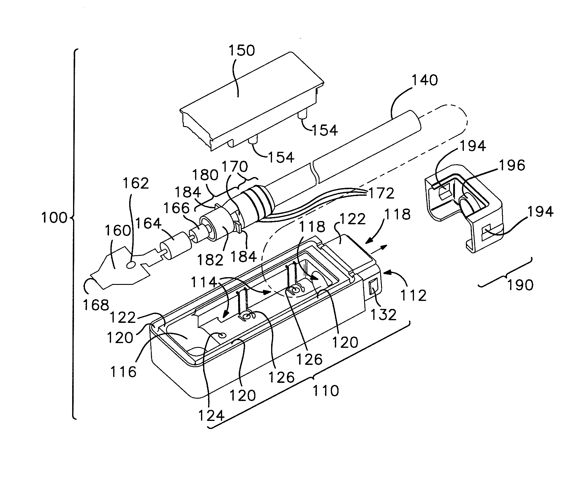
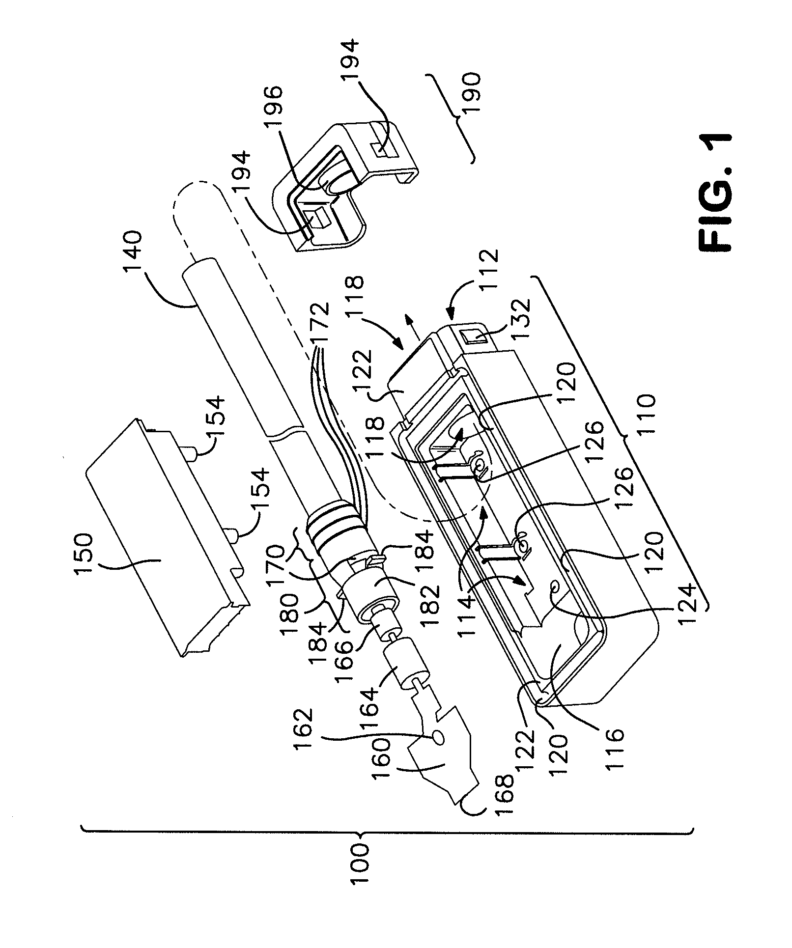
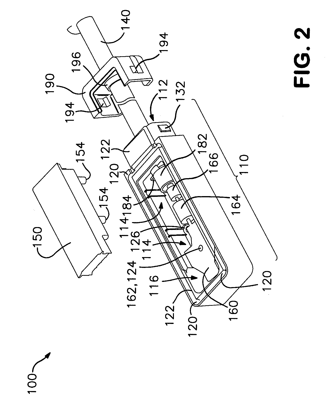
[0018]Referring to FIGS. 1-4, one embodiment of a solar module connector 100 of the present invention is shown. The solar module connector 100 includes a cable 140. The solar module connector 100 also includes a housing 110 having a mounting surface 122 at least a portion of which partially defines an opening 116 for facilitating contact with at least one buss lead 72 of a solar module 71 (see FIG. 7), a cavity 114, a cable end 112, and a passageway 118 between the cavity 114 and the cable end 112. In this embodiment, the solar module connector 100 also includes a cover 150 mounted to the housing 110 over at least a portion of the cavity 114. The housing 110 and the cover 150 together cooperate to define the opening 116 (see FIG. 3). A seal 170 is disposed around the cable 140 and is at least partially seated in the passageway 118. Additionally, a contact 160 is electrically connected to the cable 140 and disposed in the cavity 114 proximate the opening 116. In this embodiment, a ca...


PUM

PropertyMeasurementUnit
axial movementaaaaaaaaaa
lengthaaaaaaaaaa
semiconductingaaaaaaaaaa

Abstract

A solar module connector comprising: a cable; a housing having a mounting surface at least a portion of which partially defines an opening for facilitating contact with at least one buss lead of a solar module, a cavity, a cable end, and a passageway between the cavity and the cable end; a seal disposed around the cable and at least partially seated in the passageway; and a contact electrically connected to the cable and disposed in the cavity proximate the opening.

Description

FIELD OF INVENTION[0001]The present invention relates to an electrical connector for connecting a solar module, and more specifically, to a sealed electrical connector for connecting leads extending from a solar module.BACKGROUND OF INVENTION[0002]Solar energy production provides significant environmental and economic benefits, including, for example, reduction in natural resource consumption, reduction in the disposal of waste by-products, and decreased sensitivity to variations in fuel commodity costs. Sunlight is converted into electricity within solar modules, which may be made from a semiconducting material, for example, silicon. When sunlight hits a solar module, the semiconductor absorbs the light, and electrons are “loosened” from the semiconductor atoms causing them to flow and to generate electricity. This conversion of sunlight to electricity is referred to as the “photovoltaic effect.”[0003]A solar module has buss leads to facilitate its electrical connection. For exampl...

Claims


Application Information

Patent Timeline
Patent Type & Authority Applications(United States)
IPC IPC(8): H01R13/52H01R43/20
CPCH01R13/5205Y10T29/4921Y10T29/49208H02S40/34Y02E10/50
Inventor DUESTERHOEFT, SCOTT STEPHEN
Owner TE CONNECTIVITY CORP
Why Eureka
Try Eureka