Non-woven, self-wrapping thermal sleeve and method of construction thereof

Inactive Publication Date: 2011-11-10
FEDERAL MOGUL POWERTAIN LLC
View PDF10 Cites 64 Cited by
  • Summary
  • Abstract
  • Description
  • Claims
  • Application Information

AI Technical Summary

Benefits of technology

[0021]According to yet another aspect of the invention, a method of constructing a non-woven sleeve for routing and protecting elongate members from radiant heat and/or generating noise and vibration is provided. The method includes: forming a wall of non-woven material; forming first regions in the wall from a first material; forming second regions in the wall from a second material different from the first material; and heat-setting the wall into the tubular configuration.
[0022]In accordance wi

Problems solved by technology

It is known that wires and wire harnesses carried in sleeves in vehicles, such as in automobiles, aircraft or aerospace craft, can be exposed to potentially damaging radiant heat and can produce undesirable noise while the vehicle is in use.
The noise typically stems from the wires or harnesses vibrating against the sleeve and/or adjacent components, wherein the vibration results from vibrating components in the vehicle, and in the case of automotive vehicles, movement of the vehicle over a ground surface.
Unfortunately, applying tape is labor intensive, and thus, costly.
In addition, the appearance of the tape can be unsightly, particularly over time as the tape wears.
Further, in service, tape can provide difficulties in readily ac

Method used


Image

  • Non-woven, self-wrapping thermal sleeve and method of construction thereof
  • Non-woven, self-wrapping thermal sleeve and method of construction thereof
  • Non-woven, self-wrapping thermal sleeve and method of construction thereof

Examples


Embodiment Construction

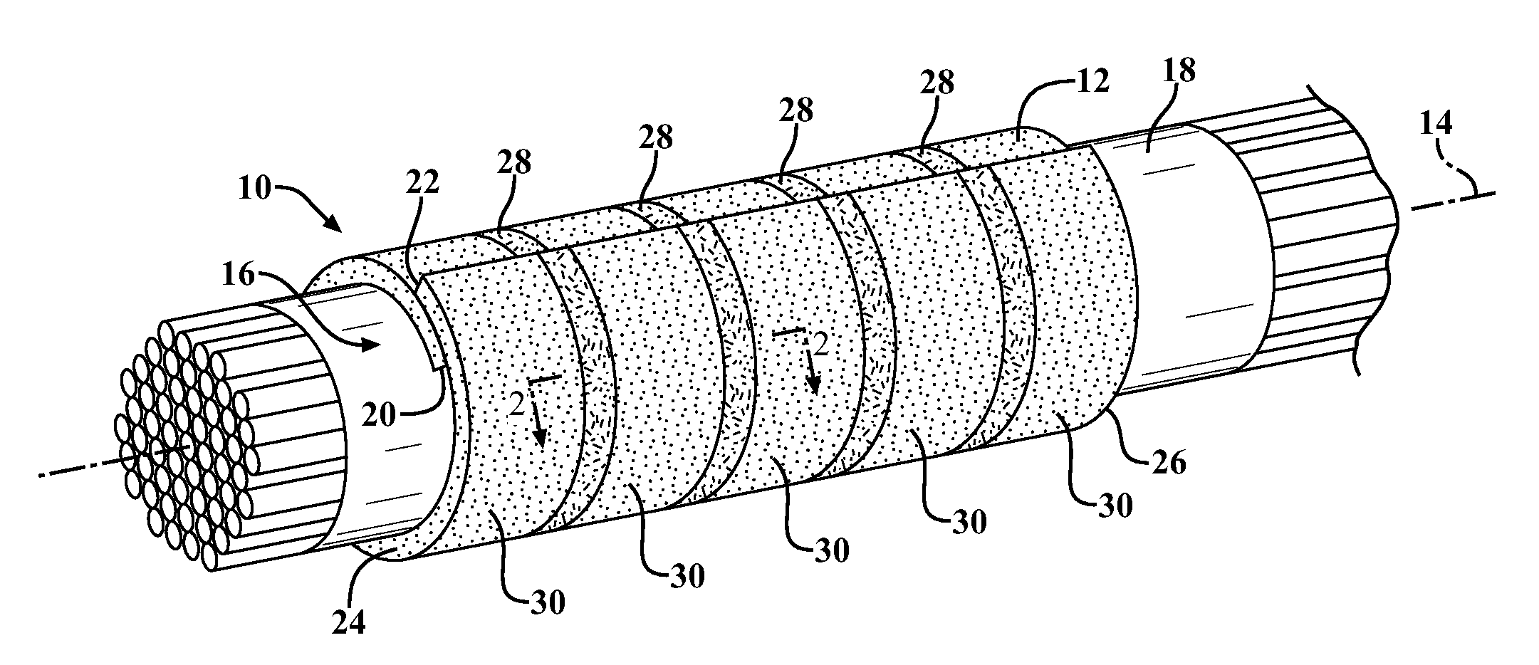
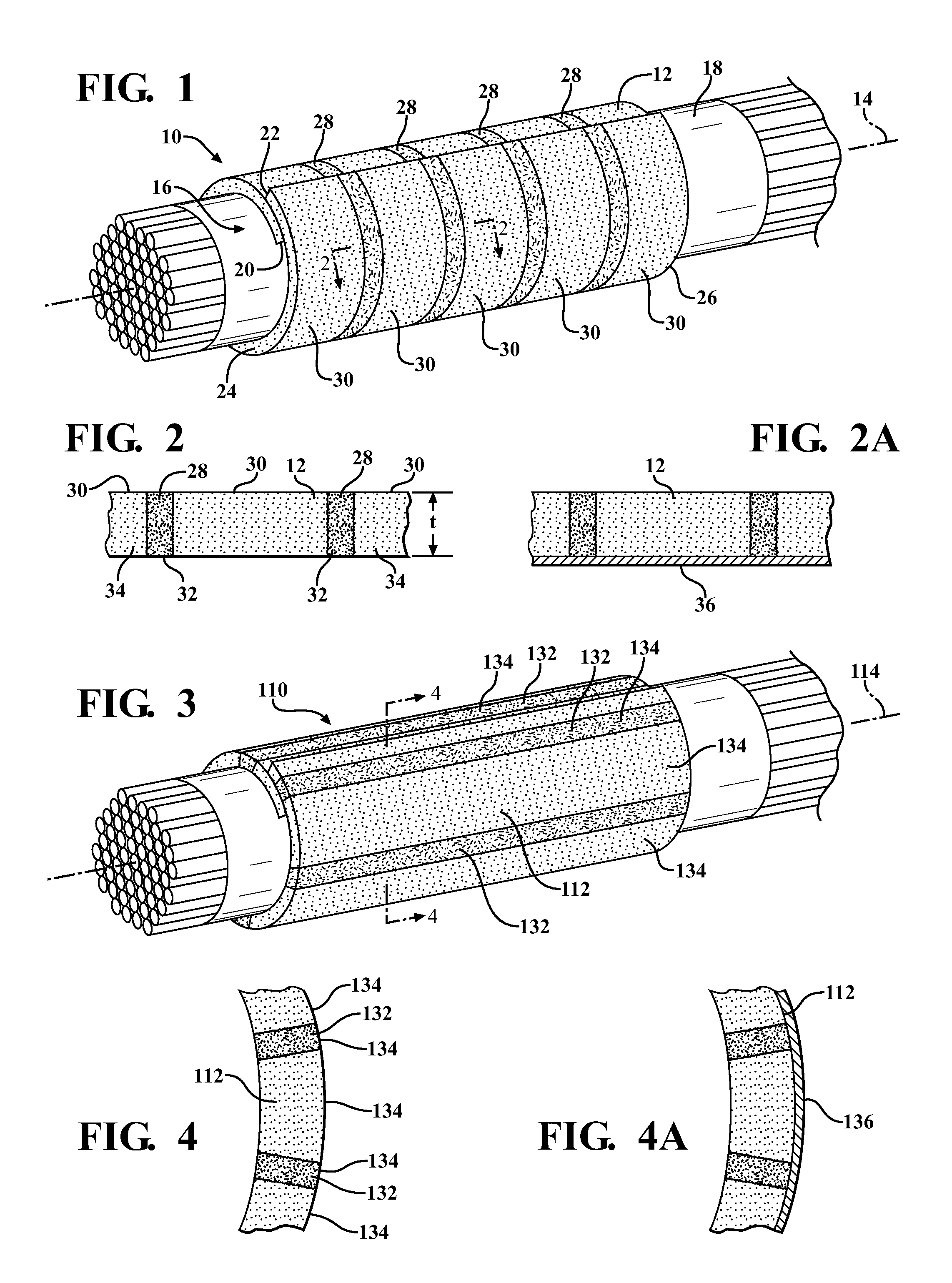
[0042]Referring in more detail to the drawings, FIG. 1 shows a non-woven, self-wrapping protective thermal sleeve, referred to hereafter as sleeve 10, constructed in accordance with one aspect of the invention. The sleeve 10 has a non-woven substrate layer, referred to hereafter as wall 12, constructed from an engineered non-woven material. The wall 12 is heat-set to take on a self-wrapping tubular “cigarette-style” configuration about a central longitudinal axis 14 to provide an enclosed tubular inner cavity 16 when the wall 12 is in a relaxed state, free of externally applied forces. The cavity 16 is readily accessible along the axis 16 so that elongate members, such as a pipe, wires or a wire harness 18, for example, can be readily disposed radially into the cavity 16, and conversely, removed from the cavity 16, such as during service. The wall 12 can be constructed of any suitable size, including length, diameter and wall thickness, wherein the wall 12 has opposite sides 20, 22 ...


PUM

PropertyMeasurementUnit
Lattice constantaaaaaaaaaa
Areaaaaaaaaaaa
Melting pointaaaaaaaaaa

Abstract

A self-wrapping, non-woven sleeve for routing and protecting elongate members and method of construction thereof is provided. The sleeve includes an elongate non-woven wall having opposite sides extending along a longitudinal axis of the sleeve. The sides are self-wrapping about the longitudinal axis to provide a tubular cavity. The sides are extendable away from one another under an externally applied force to expose the cavity for insertion of the elongate members, wherein the sides return to their self-wrapped configuration upon removal of the externally applied force. The wall includes discrete first regions of a material and discrete second regions of a material. The first and second regions of material are different and provide the wall with non-uniform physical properties.

Description

CROSS-REFERENCE TO RELATED APPLICATION[0001]This application claims the benefit of U.S. Provisional Application Ser. No. 61 / 333,019, filed May 10, 2010, which is incorporated herein by reference in its entirety.BACKGROUND OF THE INVENTION[0002]1. Technical Field[0003]This invention relates generally to sleeves for protecting elongate members, and more particularly to non-woven, self-wrapping sleeves and to their method of construction.[0004]2. Related Art[0005]It is known that wires and wire harnesses carried in sleeves in vehicles, such as in automobiles, aircraft or aerospace craft, can be exposed to potentially damaging radiant heat and can produce undesirable noise while the vehicle is in use. The noise typically stems from the wires or harnesses vibrating against the sleeve and / or adjacent components, wherein the vibration results from vibrating components in the vehicle, and in the case of automotive vehicles, movement of the vehicle over a ground surface. As such, it is custo...

Claims


Application Information

Patent Timeline
IPC IPC(8): B32B5/26B65H81/06D04H13/00
CPCH02G3/0481B60R16/0215D10B2505/12D10B2403/0122D10B2403/0311D04B21/12D10B2401/041Y10T442/494Y10T442/60H02G3/04
Inventor HARRIS, DAVID A.STAUDT, ERIC K.
Owner FEDERAL MOGUL POWERTAIN LLC
Why Eureka
Try Eureka