
Communication unit and method for selective frequency synchronization in a cellular communication network

Active Publication Date: 2011-11-10
IP ACCESS LTD
View PDF72 Cites 38 Cited by
  • Summary
  • Abstract
  • Description
  • Claims
  • Application Information

AI Technical Summary

Benefits of technology

[0020]Accordingly, the invention seeks to mitigate, alleviate or eliminate one or more of the abovementioned disadvantages singly or in any combination.

Problems solved by technology

Although VCTCXOs are inexpensive, and therefore an attractive frequency reference component for wireless communication unit designers, they are known to suffer from frequency drift from their quiescent operating frequency, which is dependent upon the age of, and any temperature variations affecting, the VCTCXO.
Hence, this frequency drift in the crystal oscillator needs to be carefully controlled; otherwise reference frequency drift will lead to degradation of performance in many aspects of the receiver.
Worse still, reference frequency drift may eventually render the receiver incapable of decoding received signals due to frequency drifting outside a receiver ‘lock’ range.
Moreover, from a transmission point of view, a communication unit is not allowed to transmit 3G signals at a frequency error greater than + / −0.1 parts per million, PPM, as per the 3GPP transmitter specifications for local area base stations (femto cells).
As a result, the accuracy of the reference frequency signals with which the receiver is frequency locked cannot be guaranteed, due to the likelihood of at least some of them originating from a femto cell, as opposed to a macro cell.
However, such a process would consume most of the available time during a Network Listen process for each cell.
Accordingly, it is not desirable that a femto cell DL receiver synchronises to another femto cell AP, since femto cell APs will typically employ inexpensive and therefore less accurate VCTCXO crystals.

Method used


Image

  • Communication unit and method for selective frequency synchronization in a cellular communication network
  • Communication unit and method for selective frequency synchronization in a cellular communication network
  • Communication unit and method for selective frequency synchronization in a cellular communication network

Examples


Embodiment Construction

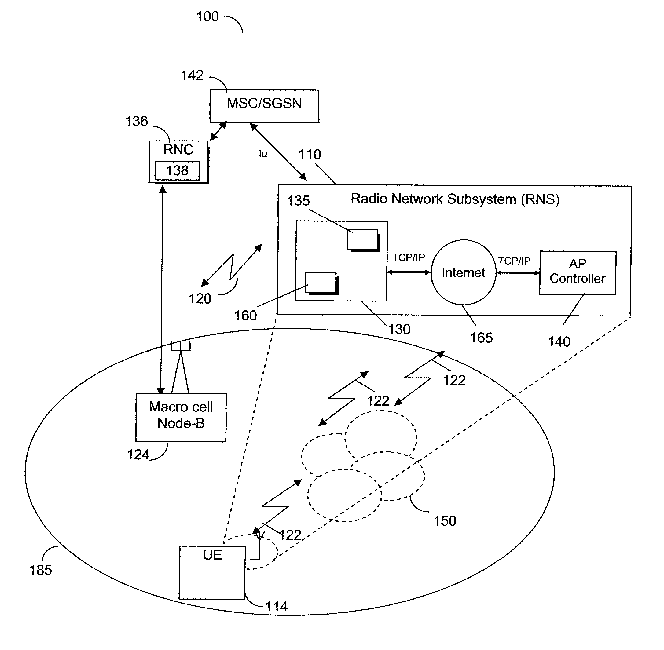
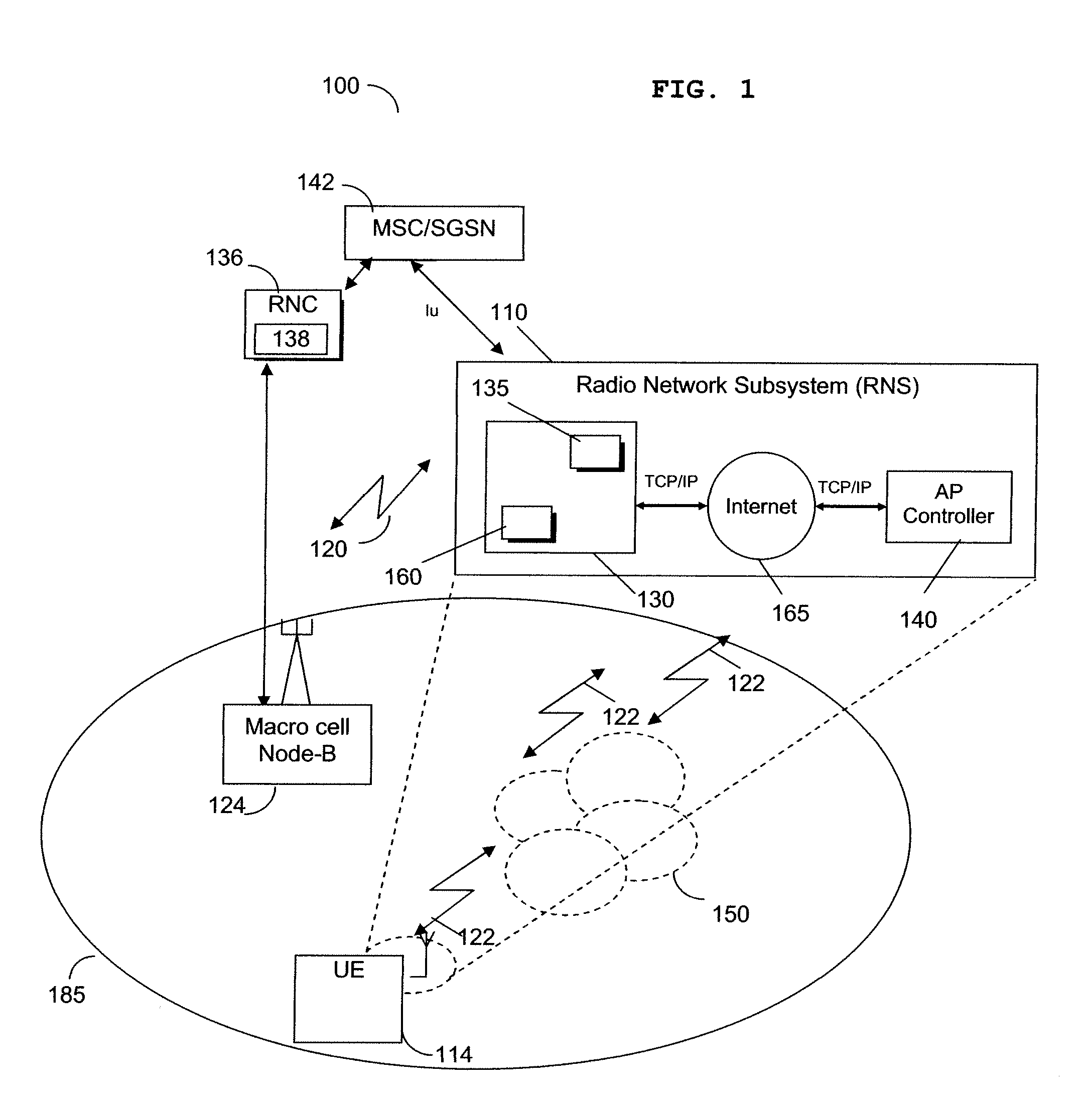
[0042]Embodiments of the invention find particular applicability in a cellular communication system that supports a number of overlapping communication coverage areas, for example a communication system that comprises a combination of femto cells and macro cells. Embodiments of the invention may be used by any communication unit needing to frequency synchronise to another communication unit. For example, embodiments of the invention may be used by a user equipment (UE) comprising a wideband code division multiple access (WCDMA) receiver. Embodiments of the invention may be employed particularly by a femto cell receiver operating in a cellular communication system comprising both femto cell base-stations (termed access points (APs) hereafter) and macro-cell NodeBs. In particular, embodiments of the invention enable a femto cell downlink receiver to synchronise to, and use as a timing reference, a macro-cell NodeB's frequency and timing transmissions, whilst disregarding femto cell AP...


PUM


Abstract

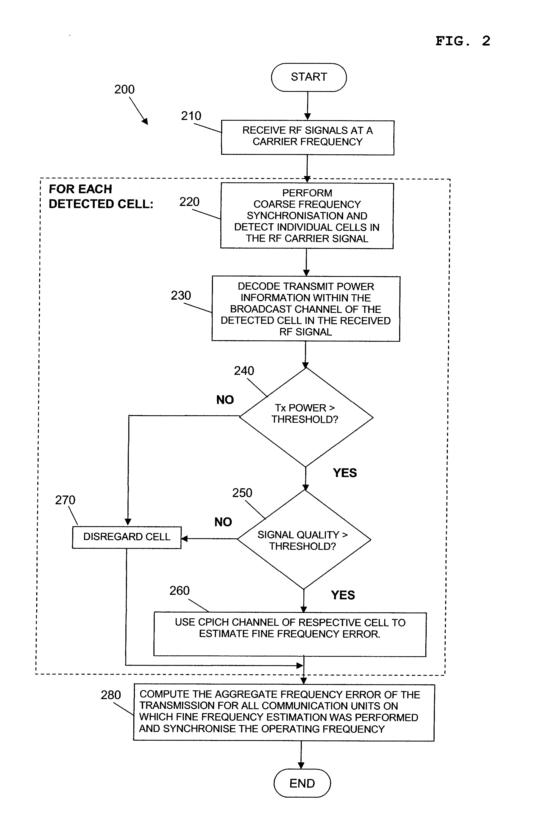
A communication unit comprises a receiver for receiving radio frequency (RF) signals from at least one wireless serving communication unit, and signal processing logic module arranged to decode information within the received RF signals is the at least one wireless serving communication unit. The signal processing logic module is further arranged to decode transmit power information in a received RF signal from the at least one wireless serving communication unit, and determine from the decoded transmit power information whether a transmission from the at least one wireless serving communication unit is suitable for use as a timing reference. If it is determined that the transmission from the at least one wireless serving communication unit is suitable for use as a timing reference, the communication unit synchronises an operating frequency to the received RF signal of the at least one wireless serving communication unit.

Description

FIELD OF THE INVENTION[0001]The field of the invention relates to a wireless communication unit and method for synchronising therein. In particular, the field of the invention relates to a 3GPP wireless communication unit synchronising to macro cell base stations in a combined macro cell / femto cell cellular communication system.BACKGROUND OF THE INVENTION[0002]Wireless communication systems, such as the 2nd Generation (2G) (otherwise referred to as Global System for Mobile (GSM) communications and the 3rd Generation (3G) of mobile telephone standards and technology, are well known. An example of such 3G standards and technology is the Universal Mobile Telecommunications System (UMTS), developed by the 3rd Generation Partnership Project (3GPP) (www.3gpp.org).[0003]Typically, wireless communication units, or User Equipment (UE) as they are often referred to in 3G parlance, communicate with a Core Network (CN) of the 3G wireless communication system via a Radio Network Subsystem (RNS)....

Claims


Application Information

Patent Timeline
IPC IPC(8): H04W52/04
CPCH04W56/0035H04B7/2687H04L7/0079H04W56/00
Inventor CHARIPADI, GOPIKRISHNABROMELL, JOHN YEARSLEY
Owner IP ACCESS LTD
Learn More