Articulating Spacer

a technology of intervertebral spacers and articulating plates, which is applied in the field of intervertebral spacers, can solve the problems of reducing the height of the nucleus, and affecting the function so as to prevent the back-out of the articulating elemen

Active Publication Date: 2011-11-10
GLOBUS MEDICAL INC
View PDF127 Cites 257 Cited by
  • Summary
  • Abstract
  • Description
  • Claims
  • Application Information

AI Technical Summary

Benefits of technology

[0008]In another embodiment, a spinal implant comprises a support body having a superior end surface and an inferior end surface. The spinal implant includes a side recess formed in the support body in between the superior end surface and the inferior end surface for receiving an articulating element therethrough. The spinal implant further includes an articulating element sized for insertion through the recess and configured to rotate along one or more axes, as well as a blocking member configured to be positioned within the recess for preventing back-out of the articulating element from within the recess.
[0009]In another embodiment, a spinal implant comprises a support body having a superior end surface and an inferior end surface, wherein each of the superior end surface and the inferior end surface includes one or more teeth, and wherein the support body includes a proximal end portion and a distal end portion having a tapered surface. A longitudinal opening can be formed through the support body, wherein the longitudinal opening is configured to receive a bone graft material. A side recess is formed in the support body between the superior end surface and the inferior end surface. The implant further comprises an articulating element sized and shaped to be received in the recess, the articulating element including an aperture with threads for receiving a portion of an insertion tool and a groove on a top portion thereof. A blocking member can be insertable through an aperture in the support body. The blocking member can be configured to prevent unintentional back-out of the articulating element from within the recess of the support body. In addition, a motion limiting member can be insertable through an aperture in the support body. The motion limiting member can be configured to contact the groove of the articulating element and to prevent over-articulation of the articulating element within the recess of the support body.

Problems solved by technology

The spinal disc can be displaced or damaged due to trauma, disease, degenerative defects or wear over an extended period of time.
The mass of a herniated or “slipped” nucleus tissue can compress a spinal nerve, resulting in leg pain, loss of muscle control, or even paralysis.
In addition, in some cases, a degenerated nucleus can lose its water binding ability and deflate, thereby reducing the height of the nucleus and causing the annulus to buckle in certain areas.

Method used


Image

  • Articulating Spacer
  • Articulating Spacer
  • Articulating Spacer

Examples


Embodiment Construction

[0027]Detailed embodiments of the invention are disclosed herein; however, it is to be understood that the disclosed embodiments are merely exemplary of the invention, which may be embodied in various forms. Therefore, specific structural and functional details disclosed herein are not to be interpreted as limiting, but merely as a basis for the claims and as a representative basis for teaching one skilled in the art to variously employ the present invention in virtually any appropriately detailed structure.

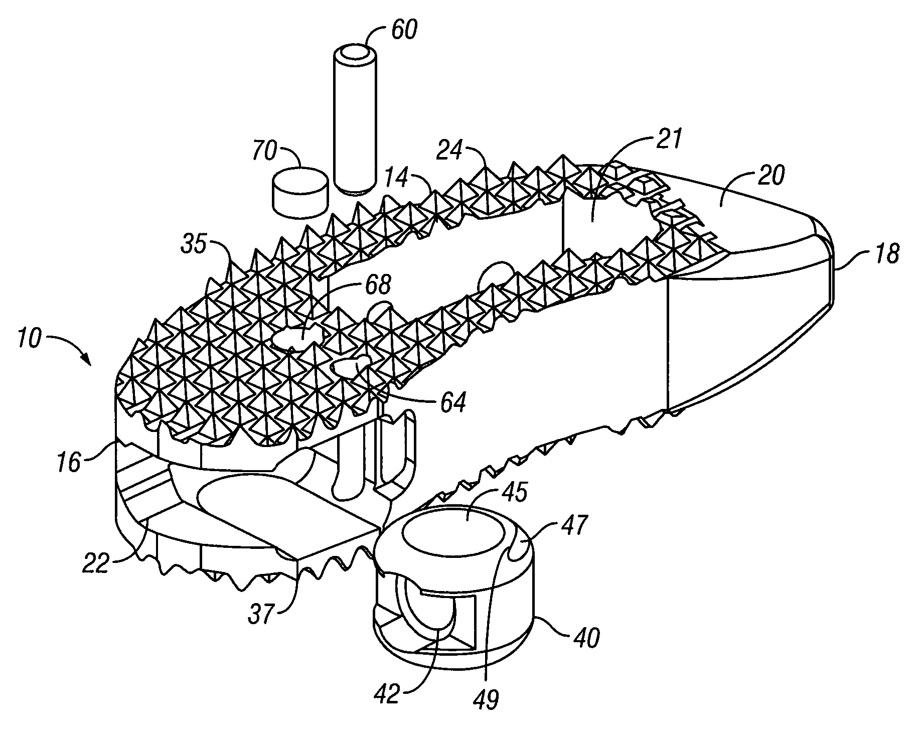
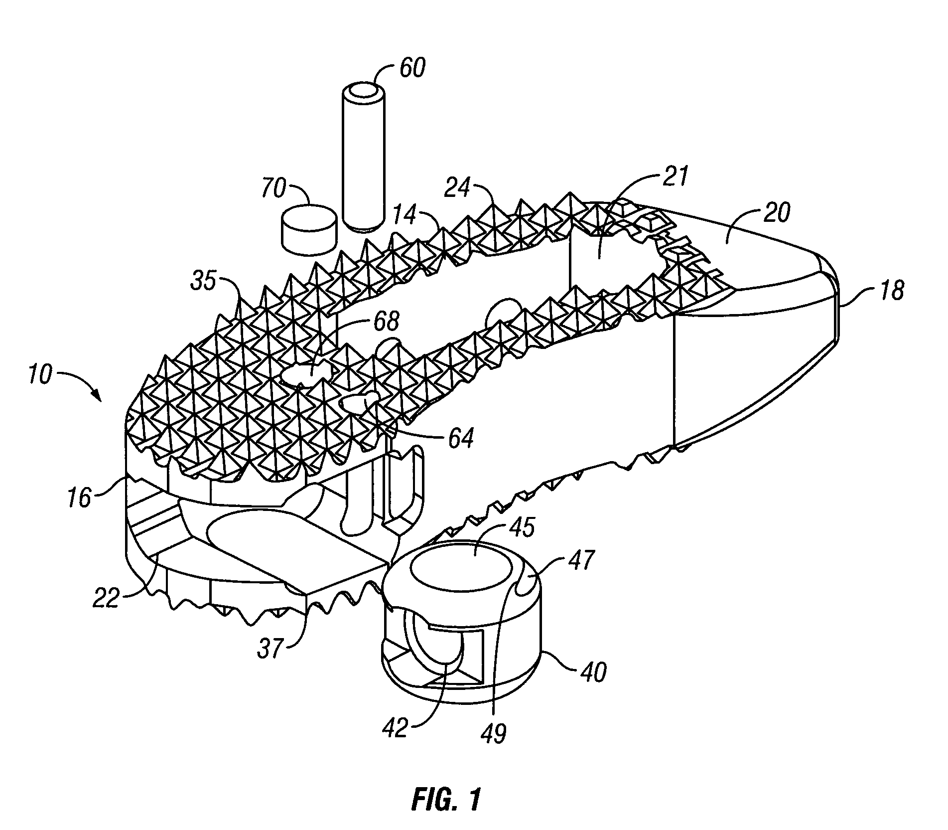
[0028]The present application generally relates to implants such as intervertebral spacers, and in particular, to articulating intervertebral spacers. The implants can be used to fuse together a treated area of the spine while restoring or maintaining the proper spacing and natural curvature of the spine. The treated area can include regions between adjacent vertebral bodies so that the height of the implant corresponds approximately to the height of the disc. Advantageously, the...


PUM


Abstract

Spinal implants are disclosed. One spinal implant includes a support body, an articulating element, a blocking member and a motion limiting member. The support body includes a superior end surface and a lower end surface having teeth. In between the superior end surface and the lower end surface is a recess formed in a sidewall of the support body for receiving the articulating element. The blocking member can be received in the recess to prevent inadvertent back-out of the articulating element from within the recess. The articulating element can articulate in one or more directions, thereby allowing articulation of the spinal implant into a desired position within a disc space.

Description

CROSS REFERENCE TO RELATED APPLICATIONS[0001]This Patent application is a continuation-in-part application claiming priority to U.S. patent application Ser. No. 12 / 250,168 filed on Oct. 13, 2008, the entire contents of which are incorporated by reference.FIELD OF THE INVENTION[0002]The present application generally relates to intervertebral spacers, and in particular, to articulating intervertebral spacers.BACKGROUND OF THE INVENTION[0003]The vertebrate spine is the axis of the skeleton providing structural support for the other parts of the body. Adjacent vertebrae of the spine are supported by an intervertebral disc, which serves as a mechanical cushion permitting controlled motion between vertebral segments of the axial skeleton. The intervertebral disc is a unique structure comprised of three components: the nucleus pulposus (“nucleus”), the annulus fibrosus (“annulus”) and two vertebral end plates.[0004]The spinal disc can be displaced or damaged due to trauma, disease, degener...

Claims


Application Information

Patent Timeline
Patent Type & Authority Applications(United States)
IPC IPC(8): A61F2/44
CPCA61F2/30734A61F2/4425A61F2/4611A61F2002/3008A61F2002/30131A61F2002/30133A61F2002/30471A61F2002/30538A61F2002/30594A61F2002/30616A61F2002/30785A61F2002/3082A61F2002/30843A61F2002/4475A61F2002/4627A61F2002/4629A61F2230/0013A61F2250/0006A61F2250/0098A61F2/4465A61F2002/30593A61F2/442A61F2/30771A61F2002/30904
Inventor NIEMIEC, MARCINADAMS, MARKIOTT, ANDREW
Owner GLOBUS MEDICAL INC
Why Eureka
Try Eureka