Power control structure for electric power tools

a power tool and control structure technology, applied in the direction of portable power tools, manufacturing tools, drilling machines, etc., can solve the problems of high cost, unsuitable for precise fabrication or handcrafted processes, complicated control structure of staged switch means, etc., and achieve the effect of improving the control structure of electric power tools

Active Publication Date: 2011-11-17
XPOLE PRECISION TOOLS
View PDF31 Cites 65 Cited by
  • Summary
  • Abstract
  • Description
  • Claims
  • Application Information

AI Technical Summary

Benefits of technology

[0005]The primary object of the present invention is to solve the problem of conventional electric power tools that have difficulty in providing precise control. The present invention provides an improved control structure for electric power tools by offering continuous and controllable output alterations.

Problems solved by technology

While they are provided respectively with a staged control structure, the staged control structure of the switch means is quite complicated.
To achieve more precise multi-staged control effect, the switch structure becomes even more complex that results in a higher cost.
The power or rotational speed are different among the stages and cannot be determined by users when in use, hence are not desirable for precise fabrication or handcrafted processes.
All the aforesaid conventional techniques provide adjustment stages that are too few in number and too large in differences between them, thus are not desirable for precise and delicate fabrication processes.

Method used


Image

  • Power control structure for electric power tools
  • Power control structure for electric power tools
  • Power control structure for electric power tools

Examples


Embodiment Construction

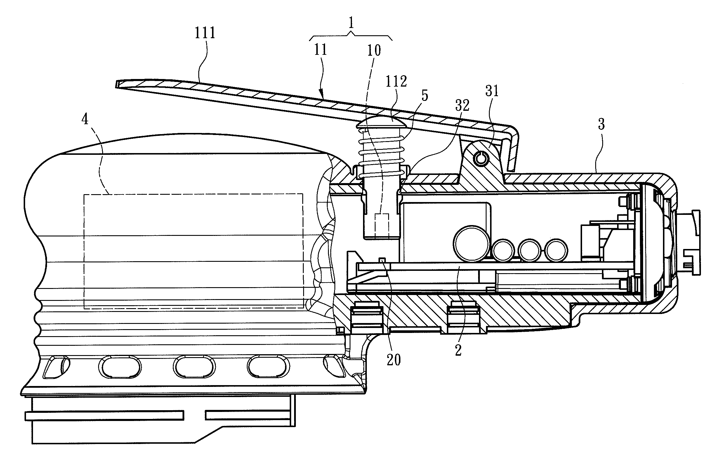
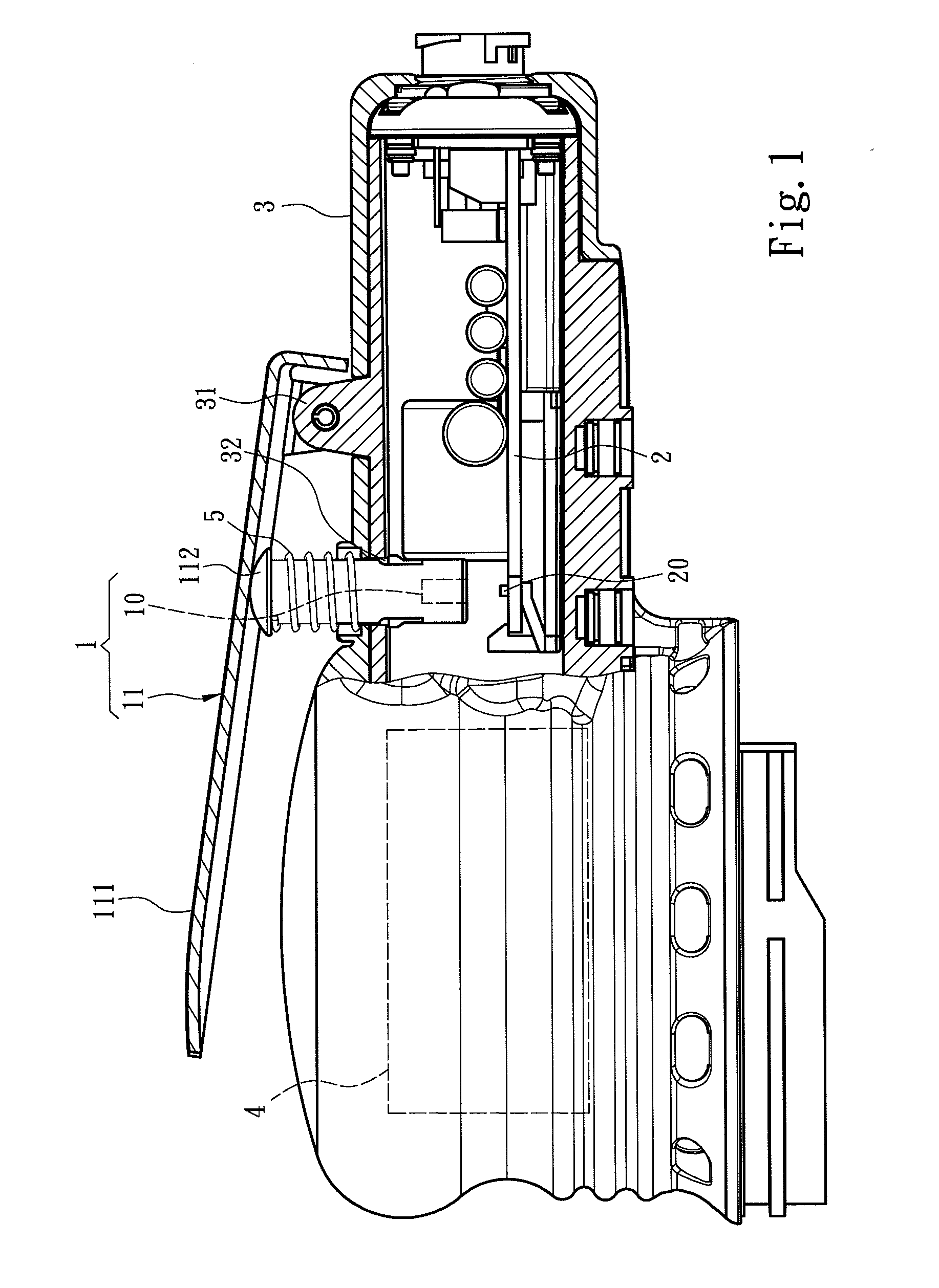
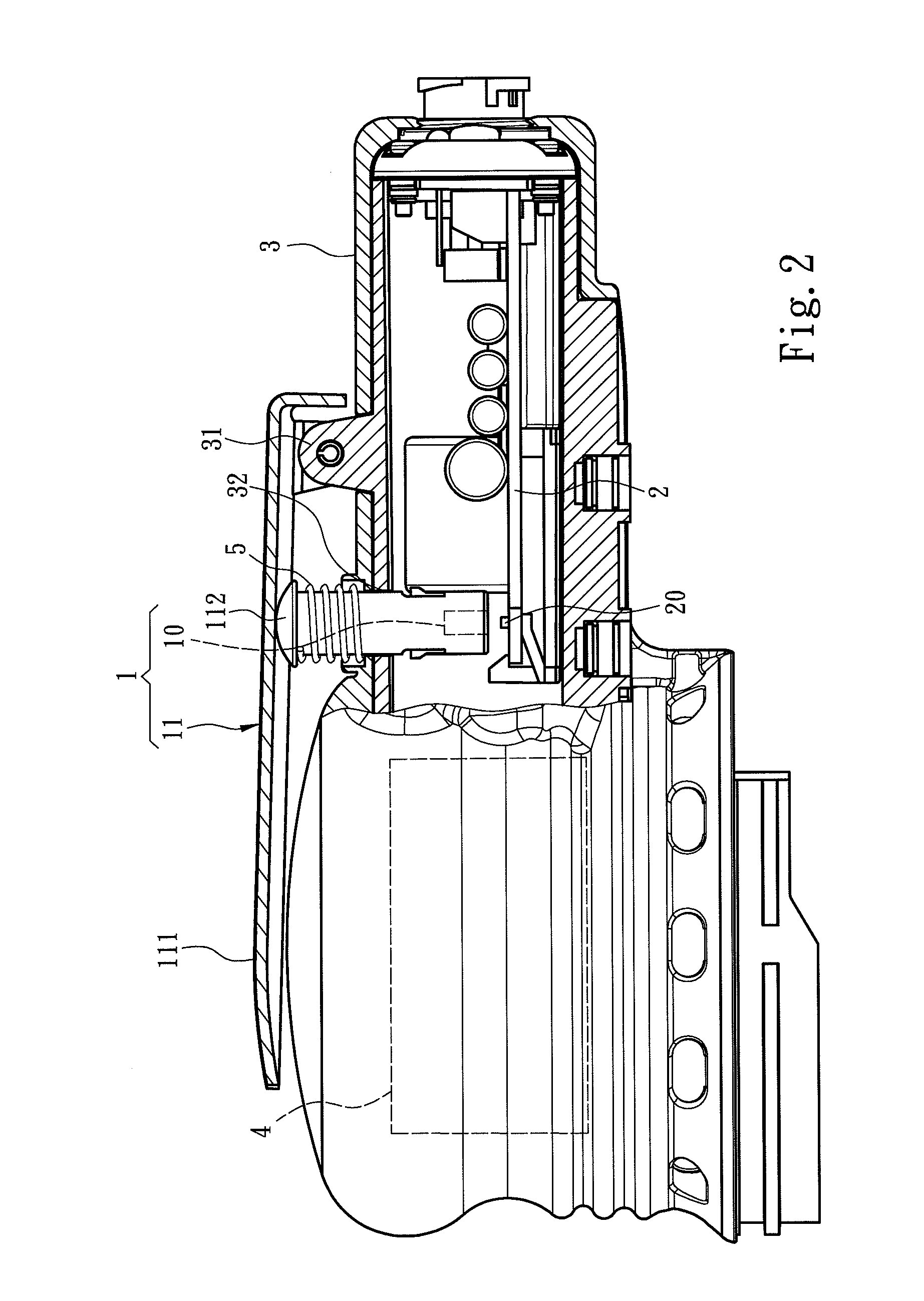
[0012]Please refer to FIGS. 1 and 2 for an embodiment of the invention. The present invention aims to provide a power control structure for an electric power tool which includes an electric motor 4 capable of coupling with various application tools (such as grinding wheels), but the adopted application tools and electric motor 4 are not the limitation of the invention. The electric power tool includes a power modulation circuit 2 to receive an input power from an electric power source 6 (referring to FIG. 3) and modulate the input power into a driving power to drive the electric motor 4 at a selected rotational speed and torque. To control the amount of the driving power, the power modulation circuit 2 is electrically connected to a magnetic control element 20. The electric power tool further includes a manual control means 1 which includes a trigger portion 11 movable by depressing of a user and a magnetic element 10 movable with the trigger portion 11. When the trigger portion 11 ...


PUM

PropertyMeasurementUnit
magnetic fieldaaaaaaaaaa
driving poweraaaaaaaaaa
external depressing forceaaaaaaaaaa

Abstract

A power control structure aims for an electric power tool which gets an input power from an electric power source and converts the input power to a driving power to drive an electric motor. The electric power tool further includes a manual control means, a magnetic control element and a power modulation circuit. The manual control means includes a trigger portion movable by depressing of a user and a magnetic element movable with the trigger portion. The magnetic control element outputs an output control signal in proportion to alterations of a magnetic field caused by movements of the magnetic element. The power modulation circuit gets the input power and modulates to the driving power controlled by the output control signal to drive the electric motor. Thus by depressing the trigger portion, output power of the electric motor can be controlled to provide precise control of rotational speed and torque alterations.

Description

FIELD OF THE INVENTION[0001]The present invention relates to a power control structure for electric power tools and particularly to a structure to achieve detailed control of electric power tools through a magnetic element and a magnetic control element incorporating with a control circuit.BACKGROUND OF THE INVENTION[0002]Small electric power tools generally are made at a small size and a lower cost and can be coupled with different application tools to form various types, such as emery wheel machines, drilling machines, electric wrenches and the like that can assist workers to carry out some work processes quickly, thus are widely adopted. Electric power tools get driving power from electricity to drive motor which further drives application tools to rotate. U.S. Pat. No. 4,667,119 entitled “Trigger switch” discloses a trigger and switch for electric power tools. The trigger includes a sleeve and a pillar housed in the sleeve. The switch includes a set of switch contacts and anothe...

Claims


Application Information

Patent Timeline
Patent Type & Authority Applications(United States)
IPC IPC(8): B27C3/08
CPCH02P23/0063B25F5/001H02P23/20
Inventor CHEN, BACH PANGHO
Owner XPOLE PRECISION TOOLS
Why Eureka
Try Eureka