Anti-Delamination Feature For Double Injection Mold Parts

a technology of anti-delamination and injection molding, which is applied in the field of double injection molding, can solve the problems of not being able to solve permanent solutions, significant chance of delamination, and easy to get easily, and achieve the effects of preventing delamination of molded parts, saving resources, and being economical

Inactive Publication Date: 2011-11-17
GOOGLE TECH HLDG LLC
View PDF10 Cites 11 Cited by
  • Summary
  • Abstract
  • Description
  • Claims
  • Application Information

AI Technical Summary

Benefits of technology

[0007]An improved anti-delamination feature and process for producing double injection molded parts is provided to prevent delamination of molded parts. Advantageously, the anti-delamination feature and process produces attractive double injection molded parts and is economical, efficient and effective.
[0008]In the anti-delamination feature and process for producing double injection molded parts, a number of round poles can be molded at the 1st shot, at a location proud from the parting line dependent on the design. These poles can be compressed down to the parting by a clamping force at the second shot. Those poles can compress between the 1st and 2nd shots to be shaped like a rivet and the undercuts of rivet poles can prevent the second shot from delamination.
[0009]A number or undercut shapes will fundamentally prevent the delamination. Even if a double injection molded part has a very thin total thickness with a very small amount of mating surface area, the undercut shape can significantly reduce the chance of delamination in use.

Problems solved by technology

A significant problem in double injection molding is that second (2nd) shot material can get easily delaminated from the first (1st) shot material in the double injection molded parts in the user's hands over time.
This technique, however, still creates a significant chance of delamination where the 1st and 2nd shots of injection molded arts are easily delamination over time and it is, therefore, not a permanent solution.
It can reduce the chance of delamination but cannot completely insure that there will be no delamination defect in field.

Method used


Image

  • Anti-Delamination Feature For Double Injection Mold Parts
  • Anti-Delamination Feature For Double Injection Mold Parts
  • Anti-Delamination Feature For Double Injection Mold Parts

Examples


Embodiment Construction

[0048]The following is a detailed description and explanation of the preferred embodiments of the invention and best modes for practicing the invention.

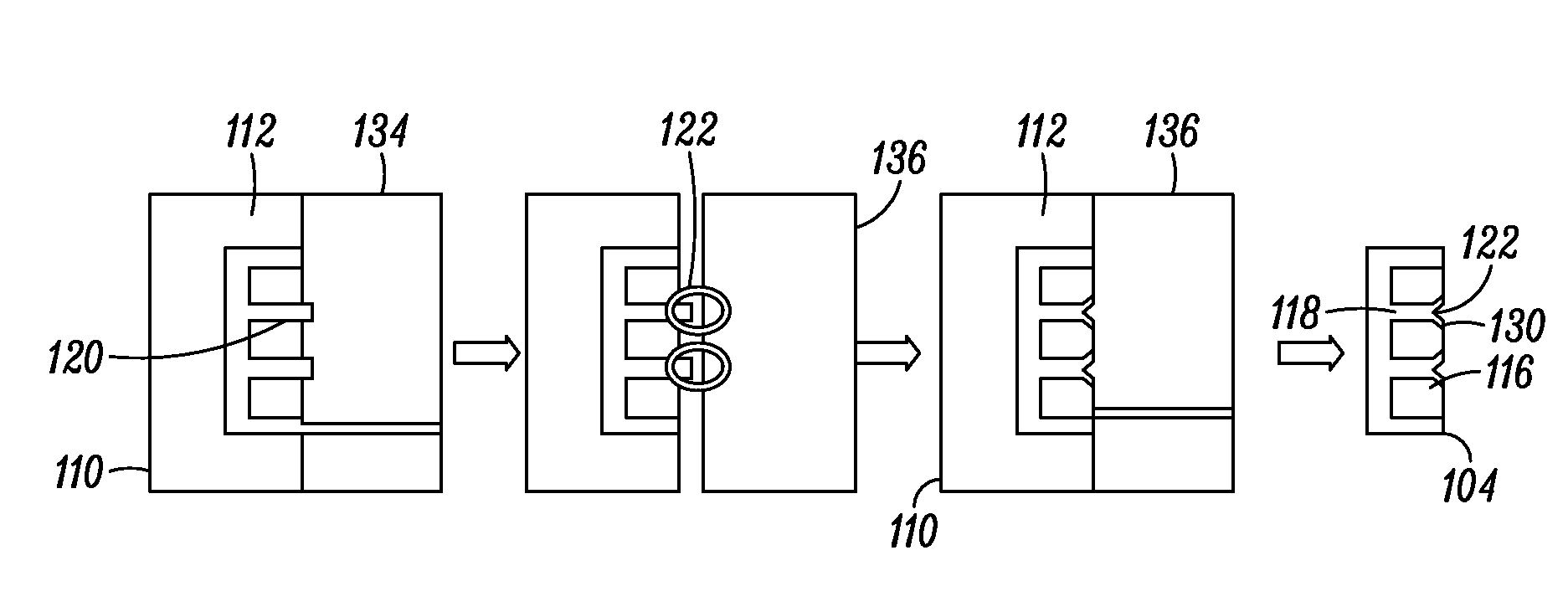
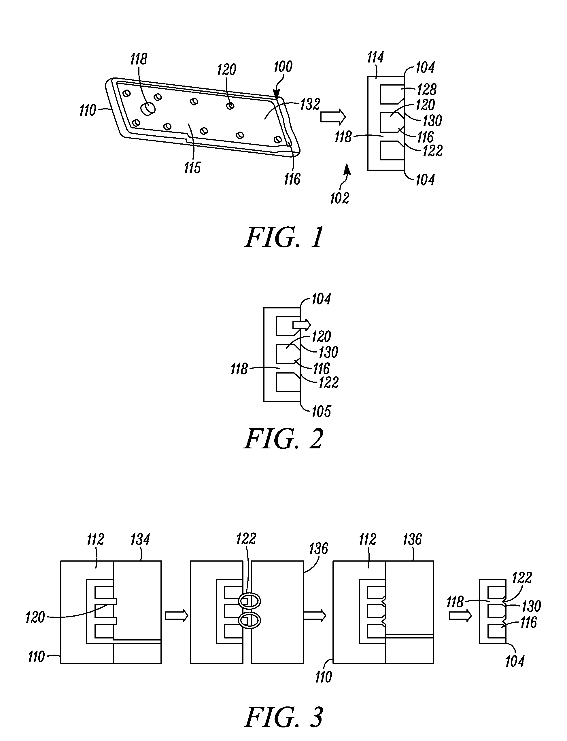
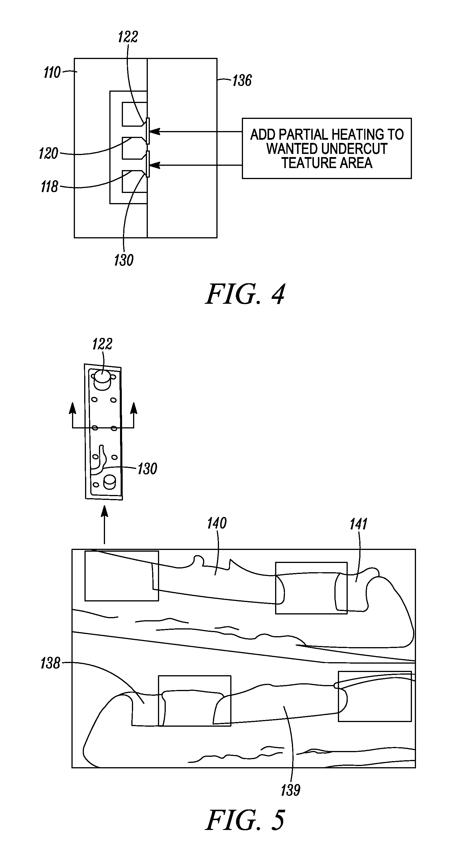
[0049]An effective economical anti-delamination feature 100 (FIG. 1) and process 102 or double injected molding is provided to mold attractive high quality products 104. While the anti-delamination process can be useful to mold many types of products, it is particularly useful to mold grommets 106 (FIG. 22) for use in an electronic communications device 108, such as one or more of the following: a mobile phone, flip phone, portable networking device, internet communications device, camera phone, clamshell device, radio telephone, cellular phone, portable game player, smart phone, portable gaming device, portable media player (PMP), personal digital assistant (PDA), wireless e-mail device, and handheld electronic device.

[0050]For grommets, the double injection mold 110 (FIGS. 1 and 2) can be provided with a grommet-shaped cavity 112. ...


PUM

PropertyMeasurementUnit
thicknessaaaaaaaaaa
maximum transverse distanceaaaaaaaaaa
clamping forceaaaaaaaaaa

Abstract

An effective economical anti-delamination feature 100 and process 102 for double injected molding is provided to mold attractive high quality products 104, such as, but not limited to, grommets 106 for use in electronic communications devices 108. In the process, after a first shot 114 is injected into a double injection mold 110, an undercut 116 comprising a delamination feature is formed in the double injection mold by tool compression or partial heating, before injecting a second shot 128 into the double injection mold.

Description

BACKGROUND OF THE INVENTION[0001]1. Field of the Disclosure[0002]This invention relates to double injection molding, and more particularly, to an anti-delamination feature and process for producing double injection molded parts.[0003]2. Background Art[0004]Double injection molding provides for use of different materials and / or colors in the molded parts allows more choices of finishes to produce more attractive and a greater variety of molded parts. A significant problem in double injection molding is that second (2nd) shot material can get easily delaminated from the first (1st) shot material in the double injection molded parts in the user's hands over time. In an effort to solve this problem, some features can be added to increase the mating surface area between the 1st and 2nd shots to reduce the chance of delamination. The features can be formed and molded copying the core shape. This technique, however, still creates a significant chance of delamination where the 1st and 2nd s...

Claims


Application Information

Patent Timeline
Patent Type & Authority Applications(United States)
IPC IPC(8): B29C45/14B29C45/16
CPCB29C45/0053B29C45/0055B29C45/1657B29L2031/3437B29C2045/0079B29C2045/1667B29K2221/003B29C45/1676
Inventor SOHN, BKLIM, KT
Owner GOOGLE TECH HLDG LLC
Why Eureka
Try Eureka