
Module to control the supply to LED assemblies

a technology of led assemblies and modules, applied in the direction of electric variable regulation, process and machine control, instruments, etc., can solve the problems of small increase in voltage applied, rise to a substantial increase in current, flow of light, etc., and achieve the effect of less complex, less cumbersome, and less cumbersom

Active Publication Date: 2011-11-17
VALEO VISION SA
View PDF3 Cites 17 Cited by
  • Summary
  • Abstract
  • Description
  • Claims
  • Application Information

AI Technical Summary

Benefits of technology

[0012]One objective of the invention includes elimination of at least some of the disadvantages which are present in the prior art, by proposing a control module which has a device for measurement of characteristic parameters of light emitting diodes, which is less cumbersome and less complex than the solutions proposed by the prior art, and consequently provides a control module which is less cumbersome and less complex.
[0018]The invention thus proposes a very compact measurement device, which can measure two or more parameters of an assembly of light emitting diodes with a single circuit which has different configurations.
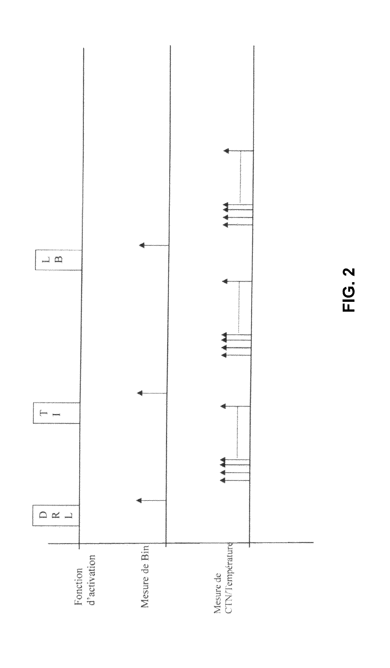
[0027]An advantage of the presence of switching means, which are preferably associated with triggering means, is that it is possible to switch from one measurement configuration to another one immediately and according to a predetermined functioning plan, in particular with a given period of acquisition and triggering of one measurement or another at certain moments (such as when switching on) of functioning of the LEDs.
[0030]The last variants show that the invention provides great flexibility of application, since the number of LED assemblies is not limited, and even with several LED assemblies, the device is economical in terms of the number of components.

Problems solved by technology

Thus, a small increase in voltage applied to the LED can give rise to a substantial increase in the current, and therefore in the flow of light.
More importantly, an excessive increase in the voltage at the terminals of the LEDs gives rise to an excessively great passage of current, which can damage the component.
Consequently, these known control circuits comprise complicated circuits and / or a plurality of quite complex electrical components.

Method used


Image

  • Module to control the supply to LED assemblies
  • Module to control the supply to LED assemblies
  • Module to control the supply to LED assemblies

Examples


Embodiment Construction

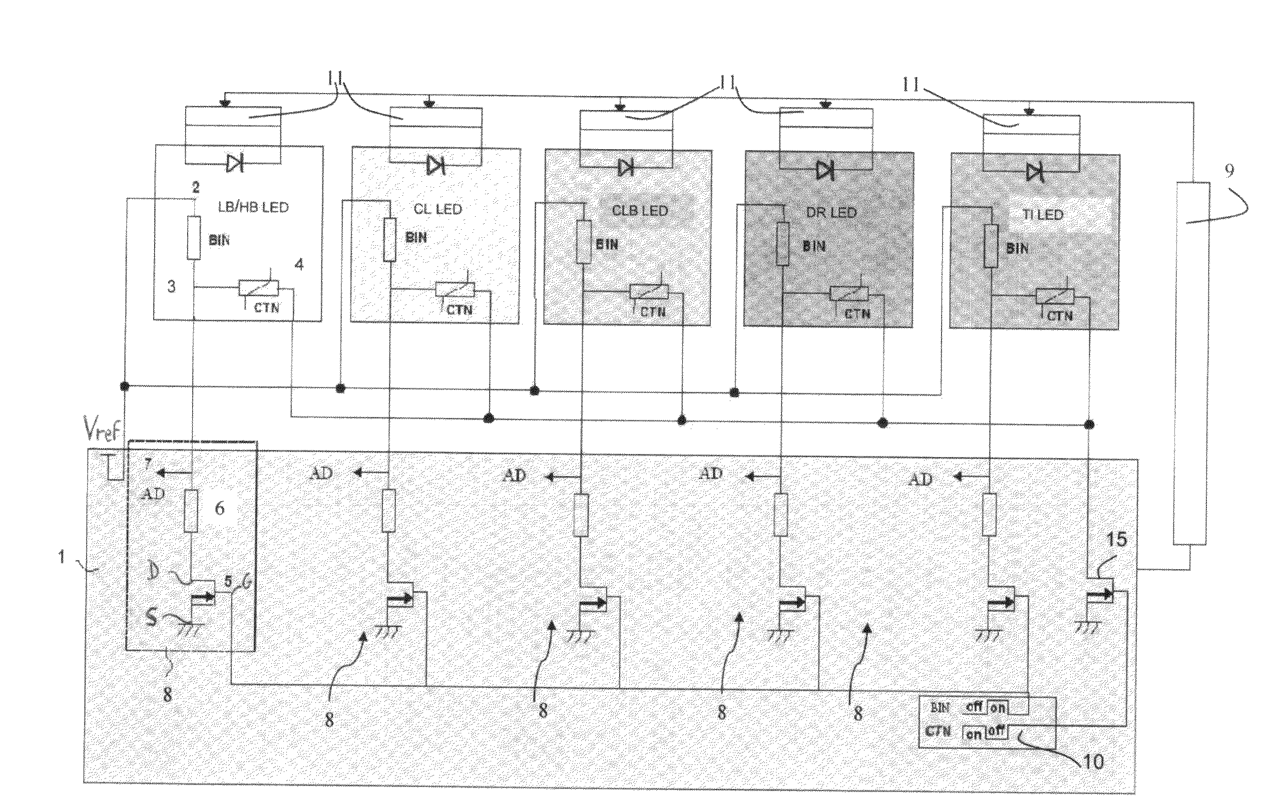
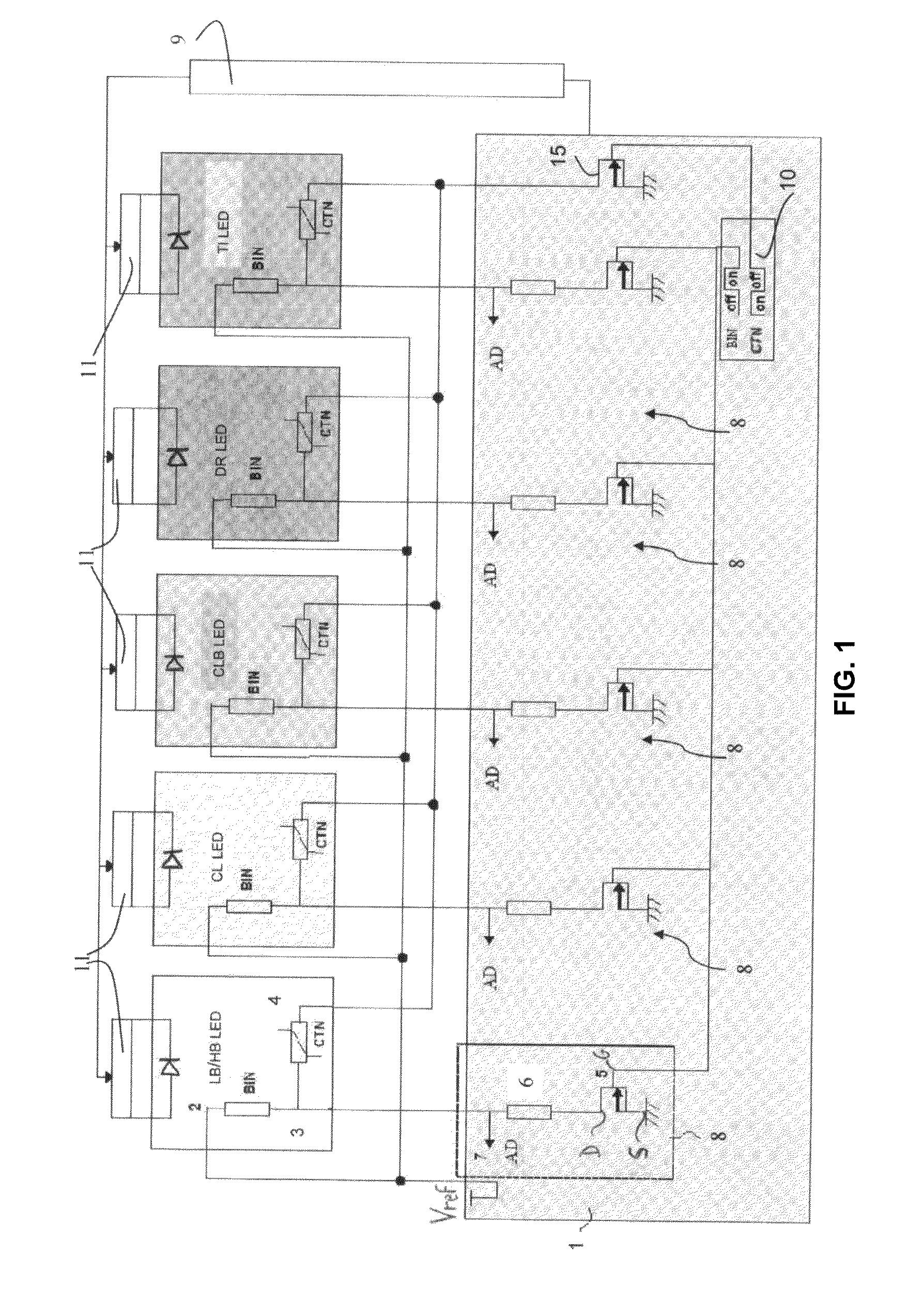
[0048]FIG. 1 shows a measurement device 1 which is connected electrically to a plurality of assemblies of different Light Emitting Diodes. From left to right, FIG. 1 shows an assembly of at least one LED for a dual function HB / LB (HB / LB for High Beam / Low Beam) module for the high-beam / low-beam function. This assembly is schematized with an LED symbol. For example, it advantageously comprises a plurality of LEDs, such as two LEDs in order to carry out the low-beam function, and one LED in order to carry out the complementary high-beam function. An assembly of at least one LED for side lighting CL LED (CL for Corner Light) is then shown for lighting of the sides, an assembly of at least one LED, CLB LED (CLB for Complementary Low Beam) for complementary lighting in low-beam mode, an assembly of at least one LED, DRL LED (DRL for Day Running Light) for a daytime position light, and an assembly of at least one LED, TI LED (TI for Turn Indicator), for the change of direction indicator. T...


PUM


Abstract

A device for measurement of characteristic parameters of at least one assembly of at least one light emitting diode (LED) comprising a measurement circuit for each assembly, wherein the measurement circuit has an electrical input which can be connected to the LED, a single measurement output to provide electrical values which are representative of at least two characteristic parameters of the LED, a first circuit configuration, which is designed to provide the measurement output with a value which is representative of a first characteristic parameter, a second circuit configuration, which is designed to provide the measurement output with a value which is representative of a second characteristic parameter and means for switching between the first circuit configuration and the second circuit configuration.

Description

CROSS-REFERENCE TO RELATED APPLICATIONS[0001]This application claims priority to French Application No. 1053738 filed May 12, 2010, which application is incorporated herein by reference and made a part hereof.BACKGROUND OF THE INVENTION[0002]1. Field of the Invention[0003]The field of the present invention is that of motor vehicle lighting. In general, the invention relates to a lighting system which is based on light emitting diodes, or LEDs. More specifically, the invention relates to a device for measurement of characteristics parameters of a light emitting diode. The invention also relates to a module to control the electrical supply to this diode, and its method.[0004]A light emitting diode (or LED) is an electronic component which can emit light when an electric current passes through it. Significant advances have made possible major new applications such as in lighting, including in motor vehicle lighting. In fact the diodes can be used to provide light, and this is one of th...

Claims


Application Information

Patent Timeline
IPC IPC(8): H05B37/02G01R31/00H05B44/00
CPCH05B33/0848H05B33/0866H05B33/086H05B45/14H05B45/24H05B45/20
Inventor DARI, ALAINFLANDRE, LOICYVON, SYLVAIN
Owner VALEO VISION SA
Learn More