System and Method for Detecting Locations of Touches on a Touch Sensor

a technology of touch sensor and location detection, which is applied in the direction of capacitance measurement, instruments, computing, etc., can solve the problems of inability to accurately detect the location of touches in electrically noisy environments, inability to accurately detect the location of touches based on measured capacitance, and inability to meet the requirements of certain applications of touch sensors, etc., to achieve noise-tolerant electrodes and low cost.

Active Publication Date: 2011-11-17
ELO TOUCH SOLUTIONS INC
View PDF7 Cites 161 Cited by
  • Summary
  • Abstract
  • Description
  • Claims
  • Application Information

AI Technical Summary

Benefits of technology

[0009]Accordingly, there is a need for low cost and higher noise-tolerant electrode touch sensor syste

Problems solved by technology

These detection algorithms may not yield accurate results in electrically noisy environments.
The calculation of coordinates of a touch based on measured capacitance is susceptible to electrical noise.
This level of distortion may be unacceptable for certain applications of the touch sensor.
The single layer backgammon-type electrode configuration can provide multiple touch capability when pairs of touches excite disjoint sets of triangular-shaped electrodes, but has difficulty when the sets of excited electrodes from two simultaneous touches are not disjoint.
For example if the triangular-shaped electrodes are aligned horizontally, detection of a pair of touches with similar vertical coordinates is problematic.
Usi

Method used


Image

  • System and Method for Detecting Locations of Touches on a Touch Sensor
  • System and Method for Detecting Locations of Touches on a Touch Sensor
  • System and Method for Detecting Locations of Touches on a Touch Sensor

Examples


Embodiment Construction

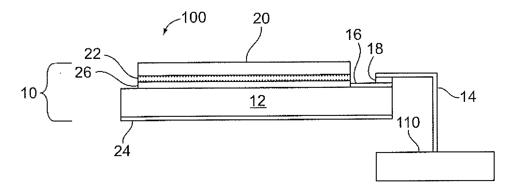
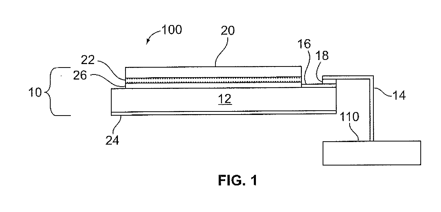
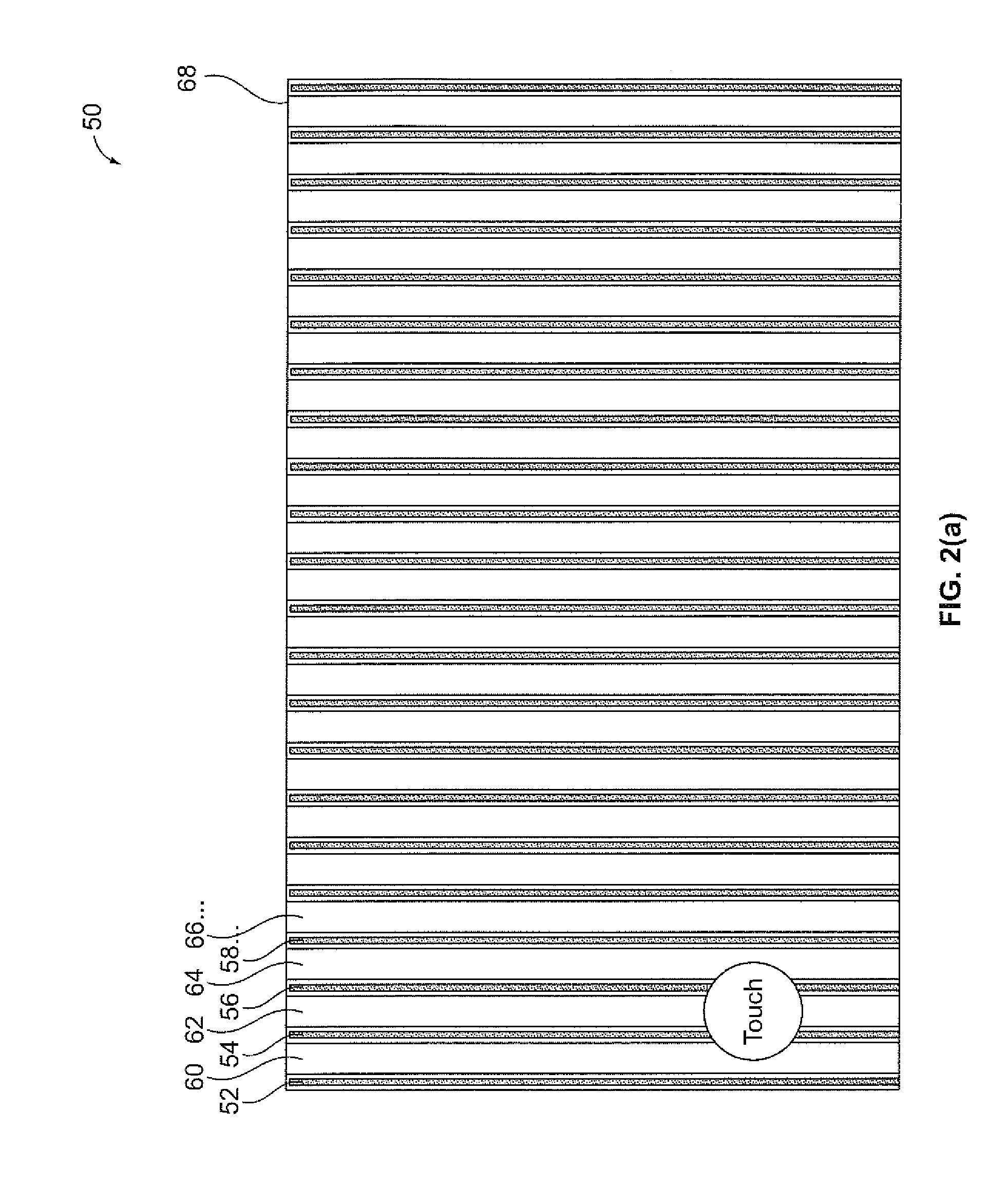
[0032]The foregoing summary, as well as the following detailed description of certain embodiments of the present invention, will be better understood when read in conjunction with the appended drawings. To the extent that the figures illustrate diagrams of the functional blocks of various embodiments, the functional blocks are not necessarily indicative of the division between hardware circuitry. Thus, for example, one or more of the functional blocks (e.g., processors or memories) may be implemented in a single piece of hardware (e.g., a general purpose signal processor or random access memory, hard disk, or the like). Similarly, the programs may be stand alone programs, may be incorporated as subroutines in an operating system, may be functions in an installed software package, and the like. It should be understood that the various embodiments are not necessarily drawn to scale or limited to the arrangements and instrumentality shown in the drawings.

[0033]As used herein, an elemen...


PUM


Abstract

A projected capacitive touch sensor system includes a substrate that defines a plurality of non-overlapping areas. Each non-overlapping area includes a plurality of detection electrodes arranged in non-overlapping columns. The columns include a horizontal detection electrode that extends along substantially an entire height of a first column, and at least a second column of at least two vertical detection electrodes that are electrically isolated from one another. The system further includes a measuring circuit configured to measure a mutual capacitance between the horizontal detection electrode and each of the at least two vertical detection electrodes in a given area. A processing logic circuit of the system is configured to determine horizontal detection electrode and vertical detection electrode combinations that have a changed mutual capacitance. The processing logic is also configured to determine the touch location based on a location of the determined horizontal detection electrode and vertical electrode combinations.

Description

RELATED APPLICATIONS[0001]This application is a continuation-in-part application of U.S. application Ser. No. 12 / 780,077, filed May 14, 2010, the contents of which are hereby incorporated by reference.BACKGROUND OF THE INVENTION[0002]The subject matter disclosed herein relates generally to touch sensors and touch sensor systems, and more particularly to projected capacitive touch sensors.[0003]In a projected capacitive touch sensor, an outer surface may be provided over one or more layers having sense electrodes or sensors formed thereon. In contrast to common resistive touch sensors, the outer surface of a projected capacitive touch sensor may be a durable glass surface having high optical transparency for viewing images displayed by an underlying display device. The touch sensor may be positioned over a display device that displays graphical selections such as buttons and icons. When a user's finger touches the outer surface at a location corresponding to a desired selection displ...

Claims


Application Information

Patent Timeline
IPC IPC(8): G06F3/044
CPCG06F3/0416G06F3/044G06F2203/04112G06F2203/04107G06F2203/04108G06F2203/04104G06F3/04164G06F3/04166G06F3/0443G06F3/0448G06F2203/04105G01R27/2605
Inventor SALAVERRY, RICARDO R.QUADERER, JAMES G.LAU, FRANCISKENT, JOEL C.
Owner ELO TOUCH SOLUTIONS INC
Why Eureka
Try Eureka