Driving Module and Driving Method

a technology of driving module and driving method, which is applied in the direction of electric digital data processing, instruments, computing, etc., can solve the problems of insufficient charging of subpixels with the most prior charging order of data driving signals sig_sb>1/b>, and insufficient charging of subpixels

a technology of driving module and driving method, which is applied in the direction of electric digital data processing, instruments, computing, etc., can solve the problems of insufficient charging of subpixels with the most prior charging order of data driving signals sig_sb>1/b>, and insufficient charging of subpixels

US20110279443A1Active Publication Date: 2011-11-17NOVATEK MICROELECTRONICS CORP

Image

  • Driving Module and Driving Method
  • Driving Module and Driving Method
  • Driving Module and Driving Method

Examples


Embodiment Construction

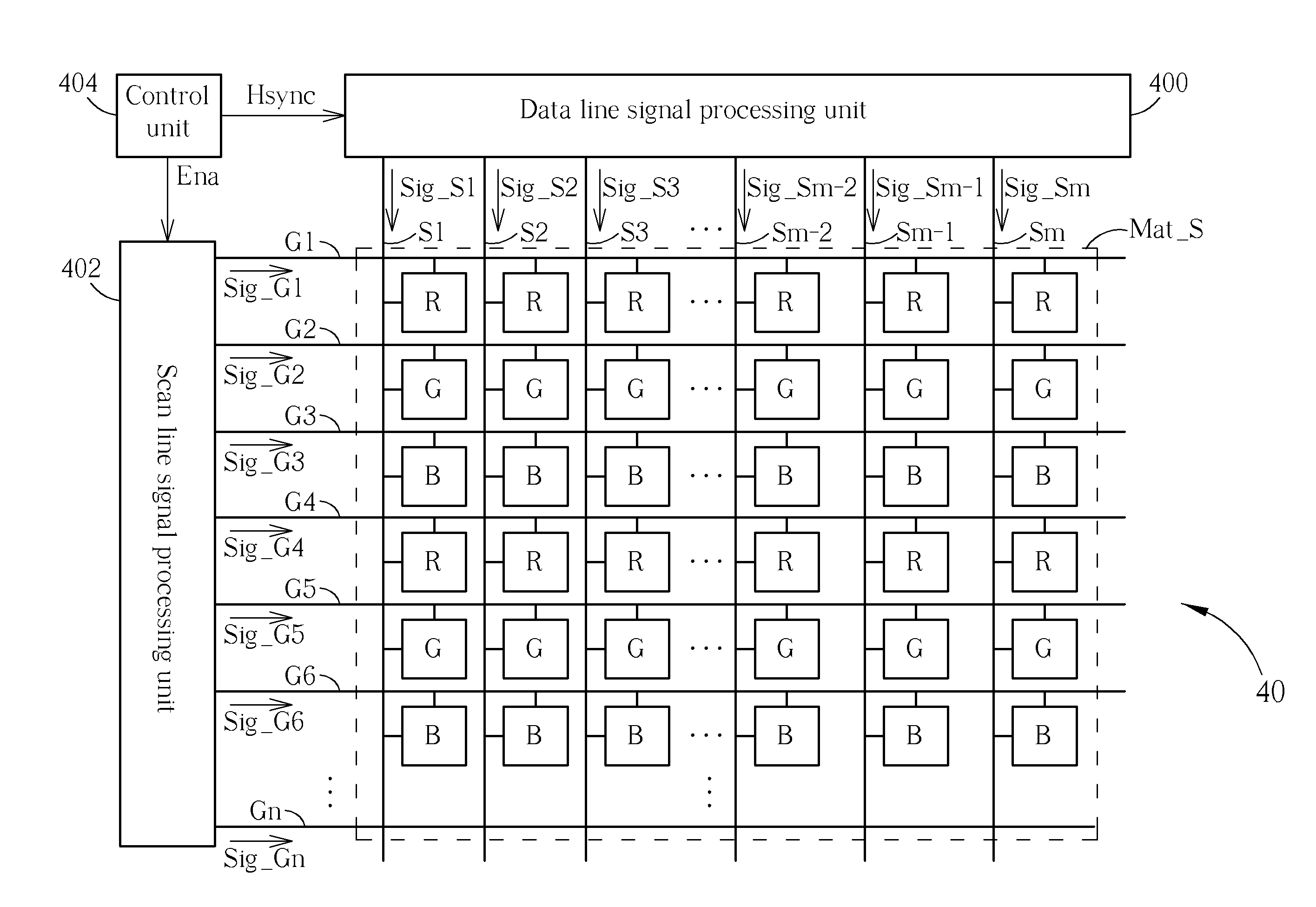
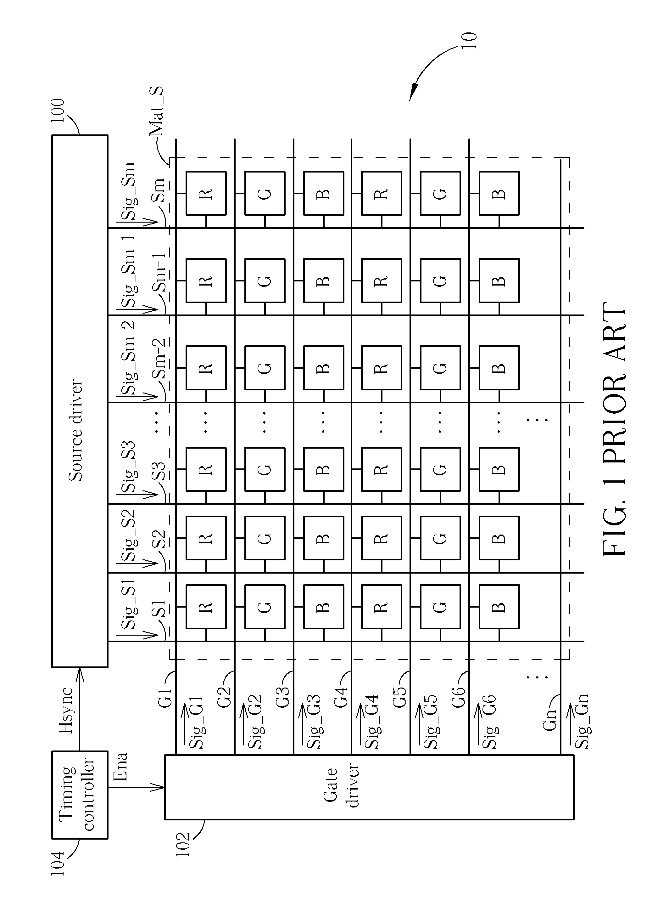
[0024]Please refer to FIG. 4, which is a schematic diagram of a driving module 40 according to an embodiment of the present invention. For clear illustration, elements with the same function and structure of those shown in FIG. 1 are denoted by the same figures and symbols in FIG. 1. The driving module 40 drives the pixel matrix Mat_S via the data lines S1-Sm and the scan line G1-Gn, to avoid charging inequality. The driving module 40 includes a data line signal processing unit 400, a scan line signal processing unit 402 and a control unit 404. The control unit 404 generates the horizontal synchronization signal Hsync and the output enable signal Ena, to control the data line signal processing unit 400 and the scan line signal processing unit 402, so as to output the data driving signals Sig_S1-Sig_Sm to the data lines S1-Sm, and output the gate driving signals Sig_G1-Sig_Gn to the scan lines G1-Gn. In order to avoid charging inequality, the control unit 404 controls the data line s...


PUM


Abstract

The present invention discloses a driving module for a liquid crystal display device. The driving module includes a data line signal processing unit, for generating a plurality of data driving signals, a scan line signal processing unit, for generating a plurality of gate driving signals, and a control unit, for controlling the data line signal processing unit and the gate line signal processing unit, such that a plurality of sub-pixels corresponding to a data line are with different charging orders in different frames, or are charged with different charging periods in a same frame.

Description

BACKGROUND OF THE INVENTION[0001]1. Field of the Invention[0002]The present invention relates to a driving module and driving method, and more particularly, to a driving module and driving method charging subpixels with different charging orders in different frames, or charging subpixels with different charging periods in a same frame, to avoid charging inequality among the subpixels.[0003]2. Description of the Prior Art[0004]A liquid crystal display (LCD) device utilizes a source driver and a gate driver to drive pixels on a panel to display images. Since cost of a source driver is higher than that of a gate driver, in order to reduce number of source drivers, a pixel structure evolves from a single gate structure to a dual gate structure or a tri-gate structure. Taking the tri-gate structure as an example, for the same number of pixels, compared to the single gate structure, the tri-gate structure only has one-third as many data lines, and thrice as many scan lines for reducing th...

Claims


Application Information

Patent Timeline
17 Nov 2011
Publication
US20110279443A1
IPC
G09G5/00
CPC
G09G3/3614; G09G3/3688; G09G2320/0242; G09G2310/0283; G09G2320/0233; G09G2310/0251
Inventors
CHANG, YU-PIN; HSIA, CHIH-PENG