Magnetoresistive element having a pair of side shields

a magnetic element and side shield technology, applied in the field of magnetic elements, can solve the problems of limiting the material and thickness, limiting the reduction of the dimension of the mr stack in the track width direction, and limiting the reliability of making the parallel track width direction parallel, so as to improve the function of the side shield

Active Publication Date: 2011-11-17
TDK CORPARATION
View PDF0 Cites 97 Cited by
  • Summary
  • Abstract
  • Description
  • Claims
  • Application Information

AI Technical Summary

Benefits of technology

[0018]It is an object of the present invention to provide a magnetoresistive element and a method of manufacturing the same, the magnetoresistive element including an MR stack and a pair of side shields disposed on opposite sides of the MR stack in the track width direction, the MR stack including a pair of free layers coupled to a pair of main shield portions, the magnetoresistive element achieving an improvement in the function of the pair of side shields, and to provide a thin-film magnetic head, a head assembly, and a magnetic recording device that each incorporate such a magnetoresistive element. While a detailed description will be given hereinafter, the present invention achieves the improvement in the function of the pair of side shields by magnetically coupling a magnetic layer included in each of the pair of side shields to a part of one of the main shield portions.

Problems solved by technology

Disadvantageously, however, this method imposes limitation on the material and thickness of the spacer layer so as to allow antiferromagnetic coupling between the pair of ferromagnetic layers.
In addition, since this method limits the material of the spacer layer to nonmagnetic conductive materials, it is applicable to neither a TMR element which is expected to provide a high output, nor a GMR element of CPP structure of current-confined-path type which is an MR element that is also expected to provide a high output and whose spacer layer includes a current-transmitting portion and a current-blocking portion.
The foregoing method further has the disadvantage that, even if it could be possible to make the directions of magnetization of the pair of ferromagnetic layers antiparallel to each other, it is difficult to make them parallel to the track width direction with reliability.
However, there is a limit to the reduction of the dimension of the MR stack in the track width direction.
Consequently, such side shield layers can fail to provide a sufficient shielding function to absorb an excessive magnetic flux.
In addition, the directions of magnetization of the side shield layers lack stability, which can make the MR element unstable in operation.

Method used


Image

  • Magnetoresistive element having a pair of side shields
  • Magnetoresistive element having a pair of side shields
  • Magnetoresistive element having a pair of side shields

Examples


first embodiment

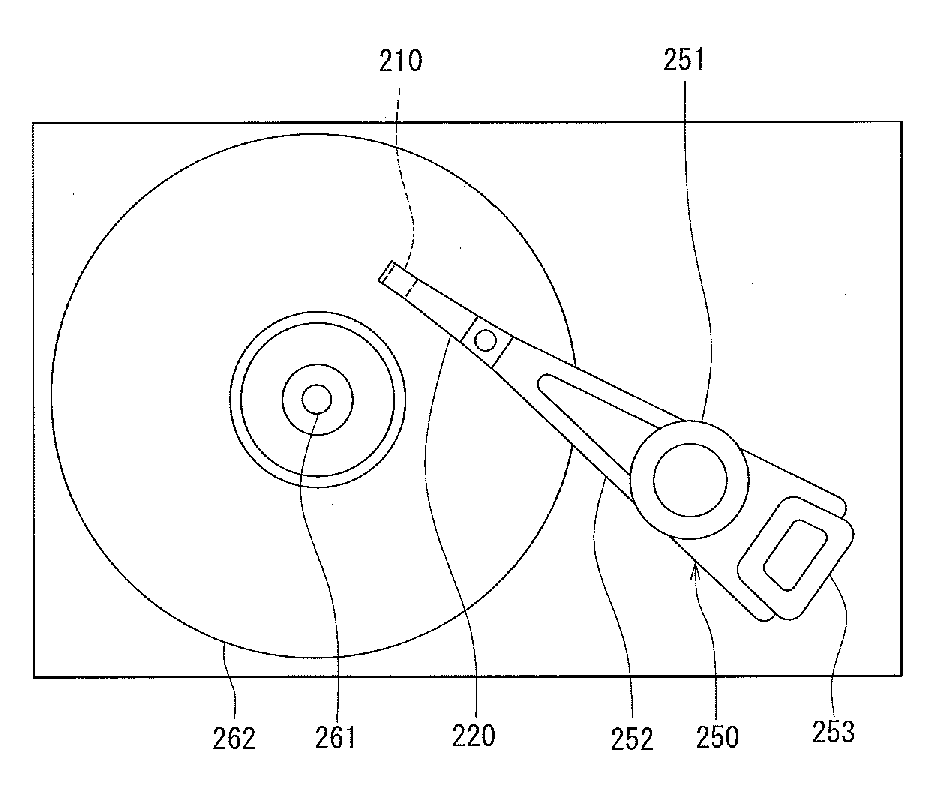
[0060]Embodiment of the present invention will now be described in detail with reference to the drawings. First, with reference to FIG. 11, a description will be given of a slider 210 including a thin-film magnetic head (hereinafter, simply referred to as a magnetic head) according to a first embodiment of the invention. The magnetic head according to the present embodiment is for use in perpendicular magnetic recording. In a magnetic recording device, the slider 210 is disposed to face a circular-plate-shaped recording medium (a magnetic disk) that is driven to rotate. The recording medium has a plurality of tracks that are arranged concentrically. The tracks are the areas where magnetic signals are to be written. In FIG. 11, the X direction is a direction across the tracks of the recording medium. The Y direction is a direction perpendicular to the surface of the recording medium. The Z direction is the direction of travel of the recording medium as seen from the slider 210, and i...

second embodiment

[0167]A second embodiment of the invention will now be described with reference to FIG. 19. FIG. 19 is a cross-sectional view showing a cross section of the MR element according to the present embodiment parallel to the medium facing surface. The MR element according to the present embodiment has a pair of side shields 191 instead of the pair of side shields 91 of the first embodiment. The pair of side shields 191 are disposed on opposite sides of the MR stack 5 in the track width direction TW, between the first main shield portion 3 and the second main shield portion 8.

[0168]Each of the pair of side shields 191 includes a side shield middle layer 193 made of a nonmagnetic conductive material, and first and second side shield magnetic layers 192 and 194 that are antiferromagnetically exchange-coupled to each other via the side shield middle layer 193. The first side shield magnetic layer 192, the side shield middle layer 193, and the second side shield magnetic layer 194 are stacked...

third embodiment

[0211]A third embodiment of the invention will now be described with reference to FIG. 24. FIG. 24 is a cross-sectional view showing a cross section of the MR element according to the present embodiment parallel to the medium facing surface. The MR element according to the present embodiment has a pair of side shields 390, a pair of nonmagnetic layers 392, and a pair of insulating layers 393, instead of the pair of nonmagnetic layers 90 and the pair of side shields 91 of the first embodiment.

[0212]The pair of side shields 390 are disposed on opposite sides of the MR stack 5 in the track width direction TW. In the present embodiment, the pair of insulating layers 4A respectively have openings for exposing part of the top surface of the first exchange coupling shield layer 74 (ferromagnetic layer 77). The pair of side shields 390 respectively have shield-coupling magnetic layers 391 that are in contact with and magnetically coupled to the ferromagnetic layer 77 of the first exchange c...


PUM

PropertyMeasurementUnit
distanceaaaaaaaaaa
distanceaaaaaaaaaa
distanceaaaaaaaaaa

Abstract

An MR element includes an MR stack disposed between first and second main shield portions, and a pair of side shields disposed on opposite sides of the MR stack in the track width direction. The first main shield portion includes a first exchange coupling shield layer that is exchange-coupled to a first antiferromagnetic layer. The second main shield portion includes a second exchange coupling shield layer that is exchange-coupled to a second antiferromagnetic layer. The MR stack includes a spacer layer, and first and second free layers with the spacer layer therebetween. The direction of magnetization of the first free layer is controlled by the first exchange coupling shield layer. The direction of magnetization of the second free layer is controlled by the second exchange coupling shield layer. Each side shield includes at least one shield-coupling magnetic layer that is in contact with and magnetically coupled to one of the first and second exchange coupling shield layers.

Description

BACKGROUND OF THE INVENTION[0001]1. Field of the Invention[0002]The present invention relates to a magnetoresistive element that is for use in, for example, a thin-film magnetic head, and has a pair of free layers and a pair of side shields.[0003]2. Description of the Related Art[0004]Recently, magnetic disk drives have been improved in areal recording density, and thin-film magnetic heads of improved performance have been demanded accordingly. Among the thin-film magnetic heads, a composite thin-film magnetic head has been used widely. The composite thin-film magnetic head has such a structure that a read head including a magnetoresistive element (hereinafter, also referred to as MR element) for reading and a write head including an induction-type electromagnetic transducer for writing are stacked on a substrate.[0005]Examples of MR elements include a giant magnetoresistive (GMR) element utilizing a giant magnetoresistive effect and a tunneling magnetoresistive (TMR) element utiliz...

Claims


Application Information

Patent Timeline
Patent Type & Authority Applications(United States)
IPC IPC(8): G11B5/33G11B21/02B05D5/12G11B5/48
CPCB82Y10/00B82Y25/00B82Y40/00G11B5/3909H01L43/12G11B2005/3996H01F10/3272H01F41/305H01L43/08G11B5/3912H10N50/10H10N50/01
Inventor MIYAUCHI, DAISUKEKAWAMORI, KEITAMACHITA, TAKAHIKO
Owner TDK CORPARATION
Why Eureka
Try Eureka