Suspension substrate, suspension, head suspension, hard disk drive, and method for manufacturing suspension substrate

a technology of suspension substrate and head suspension, which is applied in the direction of instruments, record information storage, and support for heads, can solve the problems of increasing the cost, complex process, and insufficient holes in the metal layer to adequately reduce the transmission loss, so as to increase the production cost, the effect of significantly enhancing the electrical properties of the suspension substrate or the like device and substantially facilitating the manufacture of such devices

Active Publication Date: 2011-11-17
DAI NIPPON PRINTING CO LTD
View PDF2 Cites 5 Cited by
  • Summary
  • Abstract
  • Description
  • Claims
  • Application Information

AI Technical Summary

Benefits of technology

[0007]For instance, JP2007-287280A discloses one suspension substrate intended for reducing a transmission loss of the transmission line as well as for controlling or suppressing generation of noises. This suspension substrate has holes (or micro-windows) formed in a part of a metal layer overlapped with transmission wirings. However, such provision of the holes in the metal layer is now often insufficient for adequately reducing the transmission loss.
[0008]Another suspension substrate is disclosed in JP2004-133988A. This suspension substrate is intended for reducing cross talk noises between conductive members including a first writing conductive member, a second writing conductive member, a first reading conductive member and a second reading conductive member, wherein the distance between the first writing conductive member and the first reading conductive member is set to be equal to the distance between the first writing conductive member and the second reading conductive member, while the distance between the second writing conductive member and the first reading conductive member is set to be equal to the distance between the second writing conductive member and the second reading conductive member.
[0009]JP2009-26909A discloses still another suspension substrate configured for preventing generation of the cross talk noises between the conductive members. This suspension substrate includes a first writing wiring pattern and a first reading wiring pattern, respectively arranged with a predetermined gap provided therebetween, and further includes a second writing wiring pattern and a second reading wiring pattern, respectively provided on the first writing wiring pattern and first reading wiring pattern, via the insulating layer.
[0010]However, in the suspension substrates as respectively disclosed in the above JP2004-133988A and JP2009-26909A, the conductive members (or wiring patterns) are respectively provided in a multi-layered structure. Therefore, such a structure makes the manufacturing process so complicated, leading to rather increase of the cost.
[0014]The present invention was made in light of the above circumstances. Therefore, it is an object of this invention to provide the suspension substrate, suspension, head suspension, hard disk drive and method for manufacturing the suspension substrate, respectively capable of enhancing the electric properties of each device as well as facilitating the manufacture of the device.
[0046]Therefore, according to the present invention, the electric properties of the suspension substrate or the like device can be significantly enhanced, as well as the manufacture of such devices can be substantially facilitated, without unduly increasing the production cost.

Problems solved by technology

However, such provision of the holes in the metal layer is now often insufficient for adequately reducing the transmission loss.
Therefore, such a structure makes the manufacturing process so complicated, leading to rather increase of the cost.

Method used


Image

  • Suspension substrate, suspension, head suspension, hard disk drive, and method for manufacturing suspension substrate
  • Suspension substrate, suspension, head suspension, hard disk drive, and method for manufacturing suspension substrate
  • Suspension substrate, suspension, head suspension, hard disk drive, and method for manufacturing suspension substrate

Examples


first embodiment

[0079]Now, referring to FIGS. 1 through 11, the suspension substrate, suspension, head suspension, hard disk drive and method for manufacturing the suspension substrate, respectively related to the first embodiment, will be described.

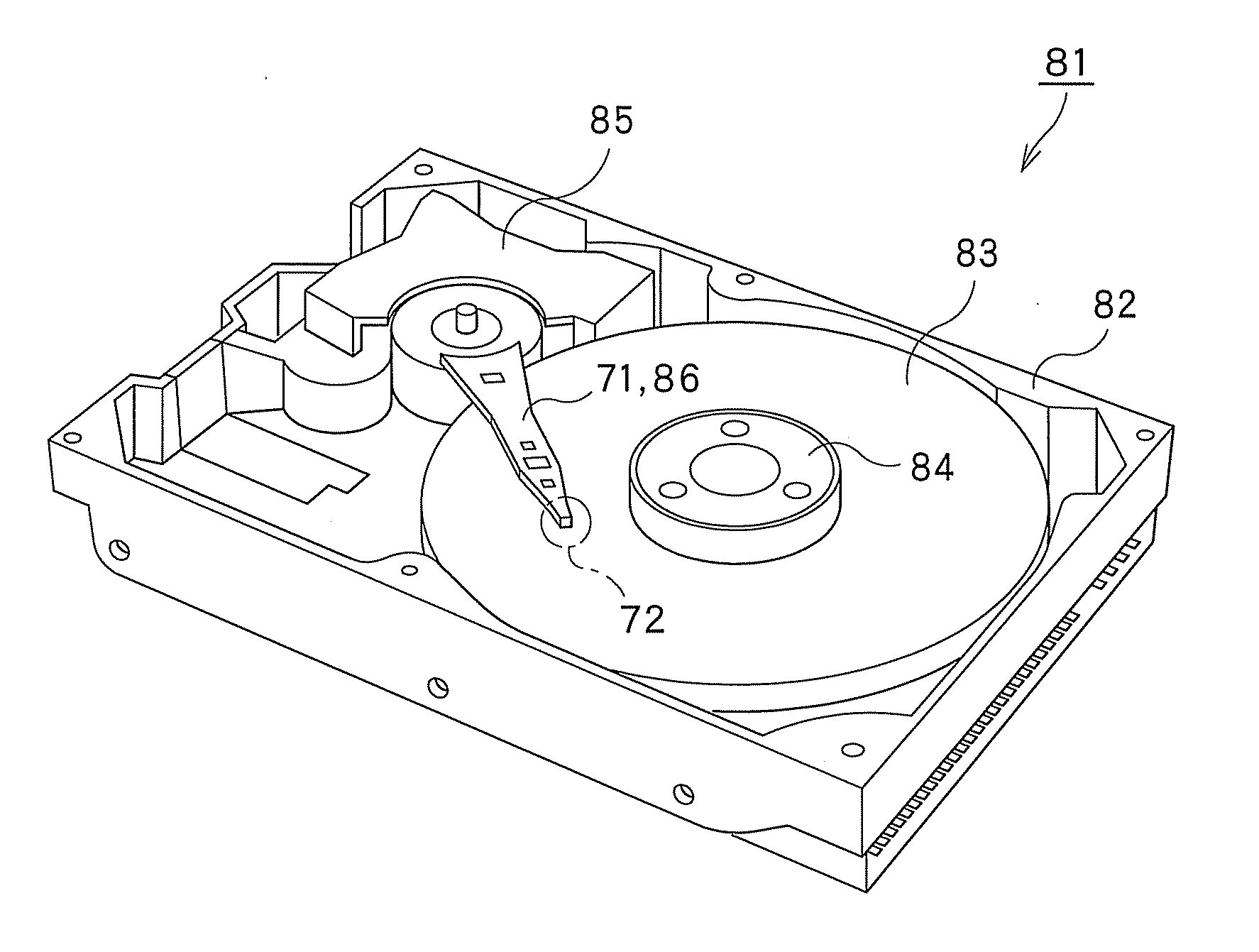
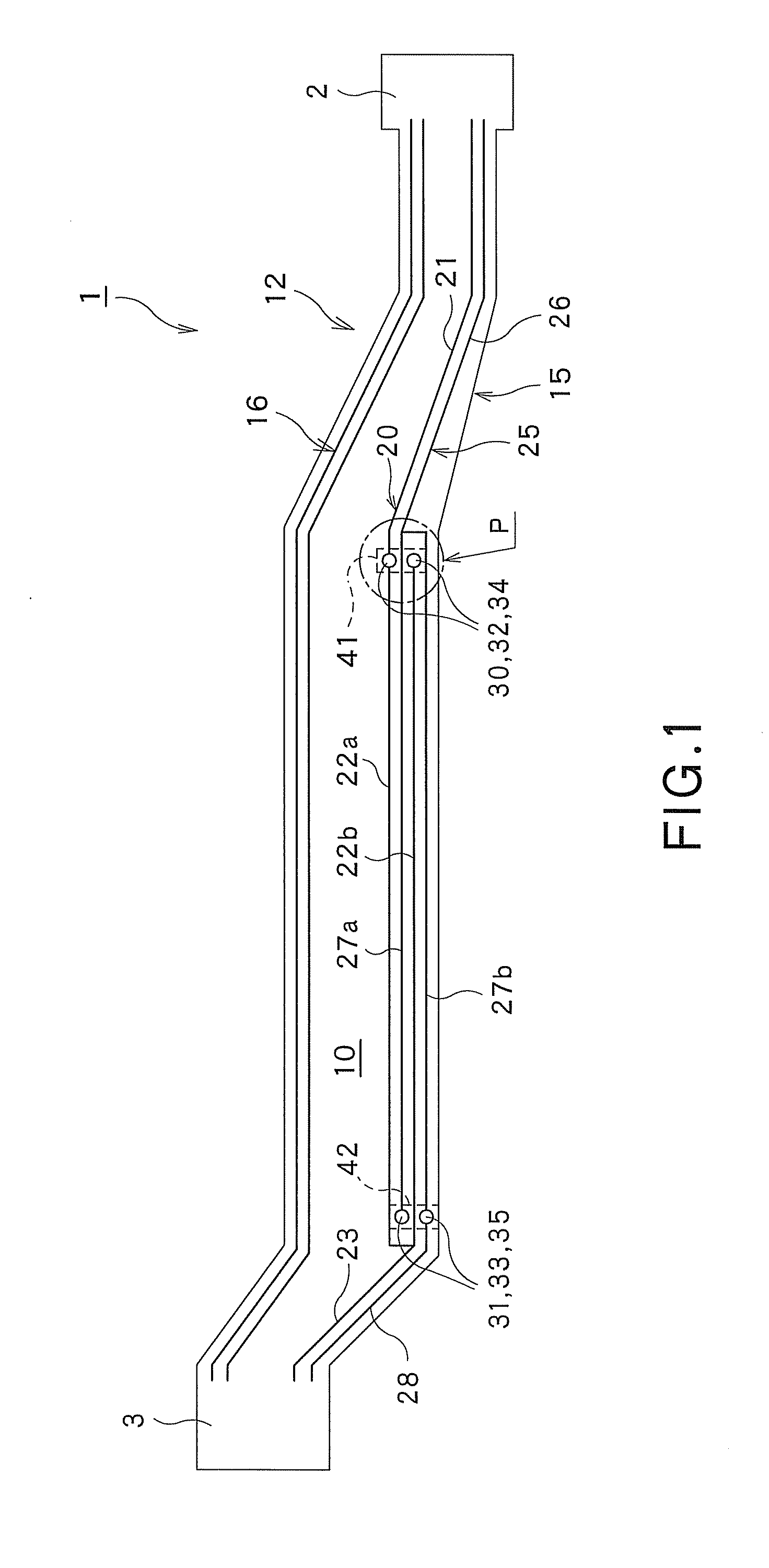
[0080]As shown in FIG. 1, the suspension substrate 1 is provided to extend from the head portion 2 on which the slider 72 that will be described later (see FIG. 6) is mounted, to the tail portion 3 to which the external connector substrate 73 is connected.

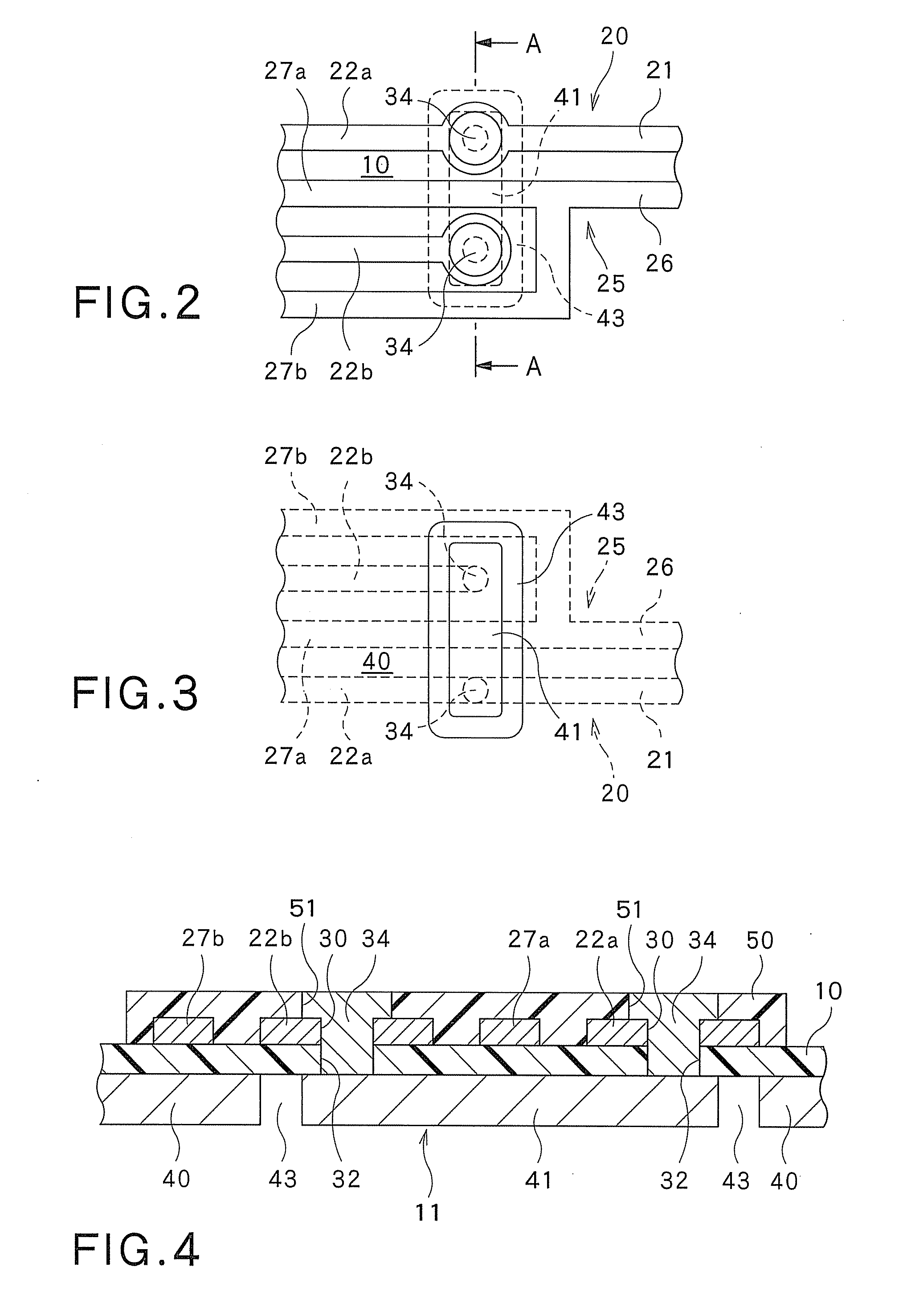
[0081]As shown in FIGS. 1 and 4, the suspension substrate 1 includes the insulating layer 10, the spring material layer (metal support substrate) 11 provided on one face of the insulating layer 10 and having the conductivity, and the plurality of (e.g., four) wirings 12 respectively provided on the other face of the insulating layer 10. Among the four wirings 12, two wirings 12 constitute the pair of writing wirings 15 (i.e., a first writing wiring 20 and a second writing wiring 25) arranged adjacent t...

second embodiment

[0115]Now, referring to FIG. 12, the method for manufacturing the suspension substrate related to the second embodiment, will be described.

[0116]Except for a key point that each wiring is formed by the so-called additive method, the second embodiment shown in FIG. 12 is substantially the same as the first embodiment shown in FIGS. 1 through 11. Therefore, in FIG. 12, each like part or portion of the first embodiment shown in FIGS. 1 through 11 is designated by each like reference numeral or character also shown therein, and the explanation on that part or portion will be omitted below.

[0117]In this embodiment, first of all, as shown in FIG. 12(a), the spring material layer 11 is prepared.

[0118]Then, the insulating layer 10 having the insulating through-holes 32, 33 is formed on the spring material layer 11 (see FIG. 12(b)). In this case, the insulating layer 10 consisting of the non-photosensitive material is first formed on the spring material layer 11, and then a pattern of a prop...

third embodiment

[0125]Next, referring to FIGS. 13 through 17, the suspension substrate related to the third embodiment of the present invention will be described.

[0126]In the third embodiment shown in FIGS. 13 through 17 one wiring, including the head-side wiring part and plurality of division wiring parts respectively bifurcated from the head-side wiring part constitutes a power source wiring for supplying the electric power to the slider. However, except for this key point, this embodiment is substantially the same as the first embodiment shown in FIGS. 1 through 11. Therefore, in FIGS. 13 through 17, each like part or portion of the first embodiment shown in FIGS. 1 through 11 is designated by each like reference numeral or character also shown therein, and the explanation on that part or portion will be omitted below.

[0127]As shown in FIGS. 13 and 14, the pair of writing wirings 15, pair of reading wirings 16 and power source wiring 90 for supplying the electric power to the slider 72 are respe...


PUM

PropertyMeasurementUnit
widthaaaaaaaaaa
thicknessaaaaaaaaaa
thicknessaaaaaaaaaa

Abstract

A suspension substrate according to the present invention includes: an insulating layer; a spring material layer provided on one face of the insulating layer and having conductivity; and a plurality of wirings provided on the other face of the insulating layer. One wiring includes a head-side wiring part extending from the head portion, and a plurality of division wiring parts respectively bifurcated from the head-side wiring part. The spring material layer includes a spring material main body, and a wiring spring material part separated from the spring material main body, via a groove. A conductive connecting part extending through the insulating layer is provided in the insulating layer. Each of the division wiring parts of the one wiring is connected with the wiring spring material part, via the conductive connecting part.

Description

CROSS REFERENCE TO RELATED APPLICATIONS[0001]This application is based on the prior Japanese Patent Application No. 2010-78879 filed on Mar. 30, 2010, the entire contents of which are incorporated herein by reference.FIELD OF THE INVENTION[0002]The present invention relates to a suspension substrate, a suspension, a head suspension, a hard disk drive, and a method for manufacturing the suspension substrate. In particular, this invention relates to the suspension substrate, suspension, head suspension, hard disk drive and method for manufacturing the suspension substrate, respectively intended for enhancing the electric properties of each device as well as facilitating the manufacture of the device.BACKGROUND ART[0003]Generally, the hard disk drive (HDD) includes the suspension substrate provided with a magnetic-head slider adapted for writing and reading data relative to a disk for storing the data therein. This suspension substrate includes a spring metal layer and a plurality of (...

Claims


Application Information

Patent Timeline
Patent Type & Authority Applications(United States)
IPC IPC(8): G11B5/48G11B5/127
CPCG11B5/486H05K1/0245H05K1/056Y10T29/49032H05K3/4007
Inventor MIURA, YOICHIHIRATA, KENRO
Owner DAI NIPPON PRINTING CO LTD
Why Eureka
Try Eureka