
Power converter

a converter and power technology, applied in the field of power converters, can solve the problems of unregulated voltages, in many cases too course or too much variation for final application, and achieve the effects of improving the smoothing of output signals, reducing the crest factor of output current, and increasing the conduction angle of output diodes

Inactive Publication Date: 2011-11-17
NXP BV
View PDF2 Cites 1 Cited by
  • Summary
  • Abstract
  • Description
  • Claims
  • Application Information

AI Technical Summary

Benefits of technology

The invention is a power converter that can generate multiple output signals with minimal modifications. It is easy to integrate and scale up. The converter includes a primary winding, two secondary circuits, and a post regulator. The post regulator includes a switch that controls power flow and is synchronized with the output signals. The second secondary circuit can generate a second output signal, which is used to open the switch. The converter can be used with a rectified mains or a separate DC source. The method for power conversion involves supplying a primary alternating voltage to the primary winding and generating a first secondary output signal, which is used to open the switch. The technical effects of the invention include easy integration, scalability, and smoothing of output signals.

Problems solved by technology

The unregulated voltages however in many cases are too course or vary too much for final application.

Method used


Image

  • Power converter
  • Power converter
  • Power converter

Examples


Embodiment Construction

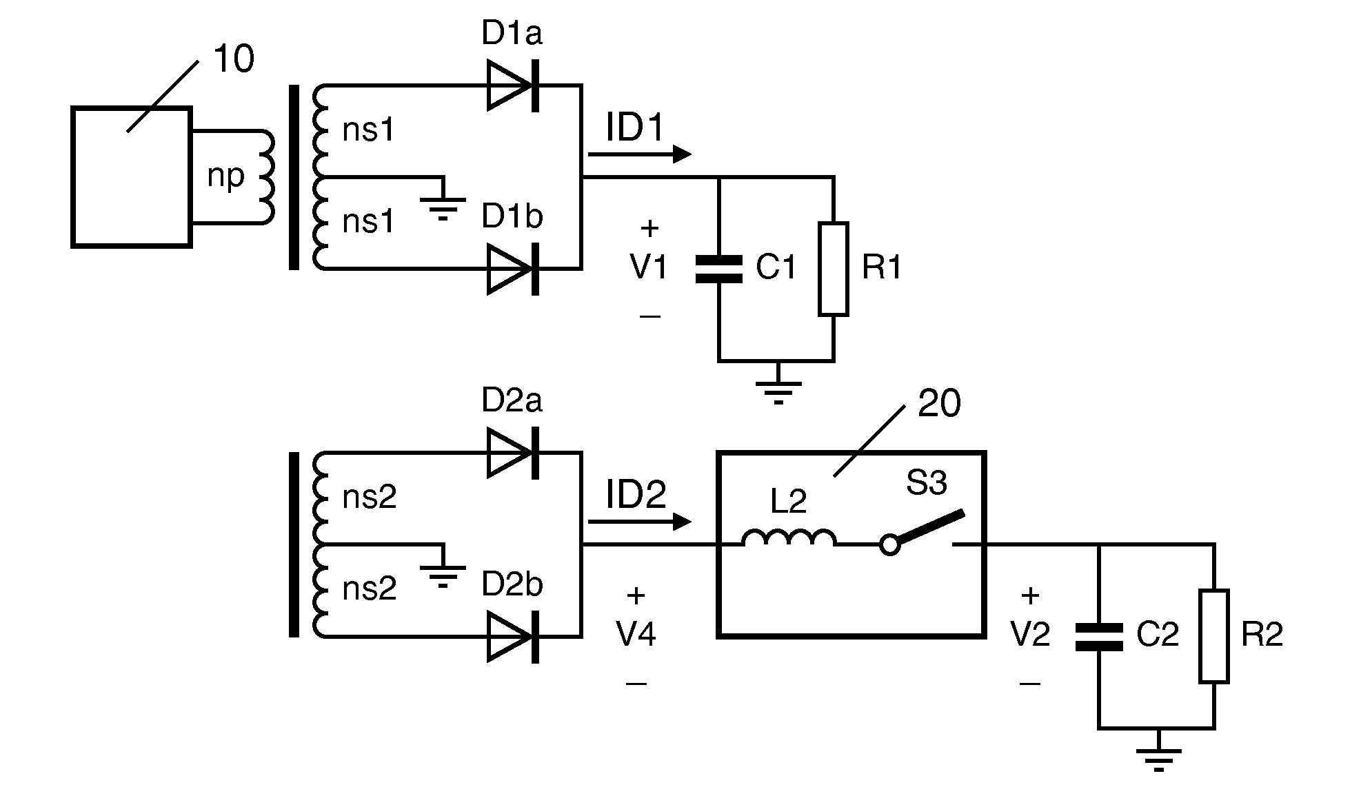
[0026]FIG. 4 depicts a power regulator according to the invention.

[0027]The power converter comprises a primary winding np, which is connected either to a conventional pulsating voltage or it is part of a series resonant circuit 10. The pulsating voltage can be the mains (50-60 Hz). Alternatively, the resonant converter can be supplied from a Direct Current (DC) source.

[0028]The power converter further comprises a first secondary winding ns1 and a second secondary winding ns2. The first secondary winding ns1 provides a first output signal ID1, which is used as a first output of the converter and as a reference signal for a second regulator as it is described hereunder. The resistor R1 and the capacitor C1 represent the load of the first output signal. The first and the second secondary windings each comprise two identical windings.

[0029]The power converter is adapted to have a second secondary winding ns2, too. The secondary winding provides a second output signal ID2. It is worthwh...


PUM


Abstract

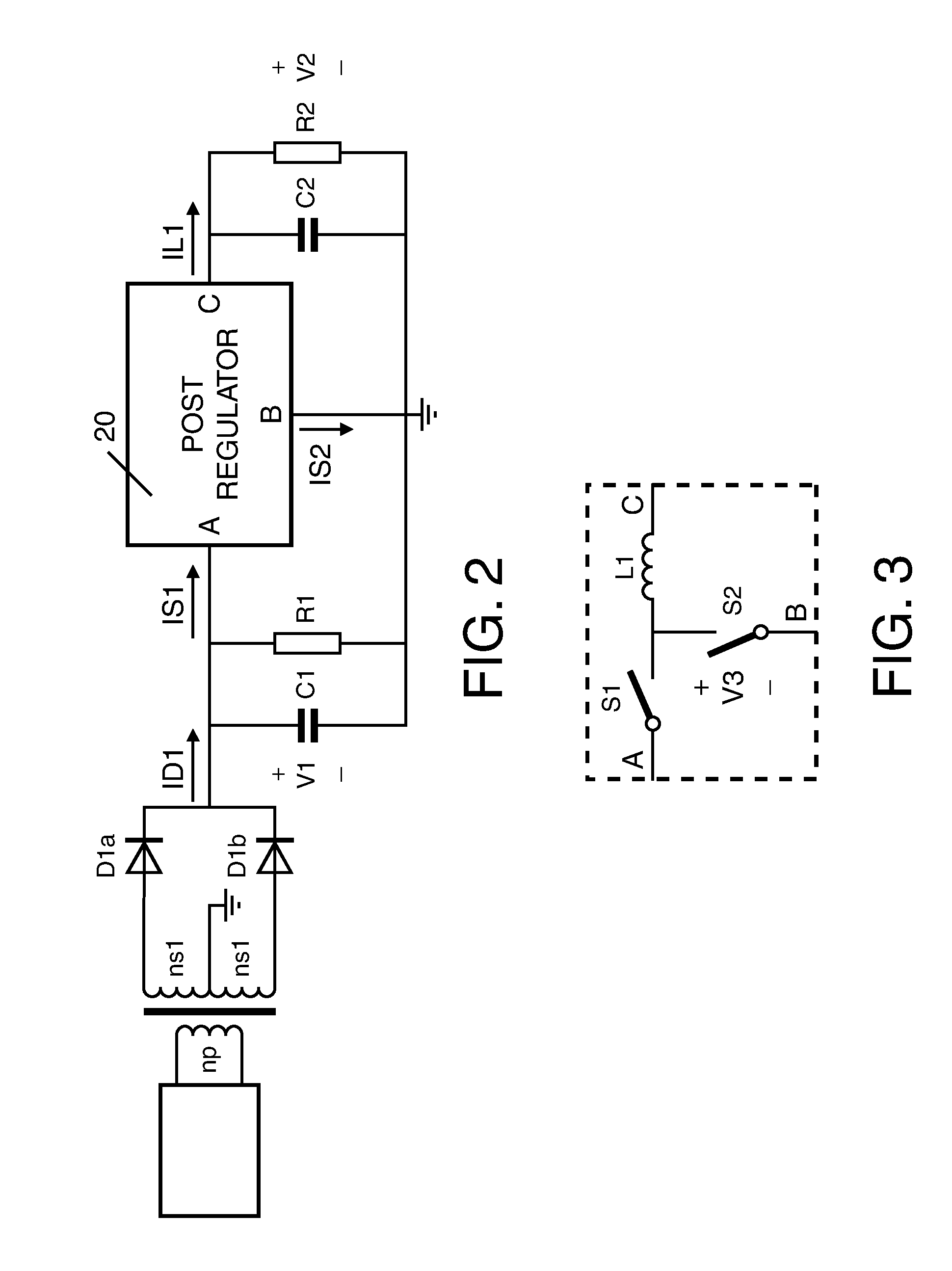
The invention refers to a power converter and to a method for power conversion. The power converter includes a primary winding adapted to receive a primary alternating voltage. The converter further includes a first secondary circuit magnetically coupled to the primary winding, the first secondary circuit generating a first secondary output signal, the power converter further includes a second secondary circuit magnetically coupled to the primary winding. The power converter includes a post regulator adapted to be coupled to the second secondary circuit, the post regulator having a switch which is opened at every zero-crossing of the first output signal.

Description

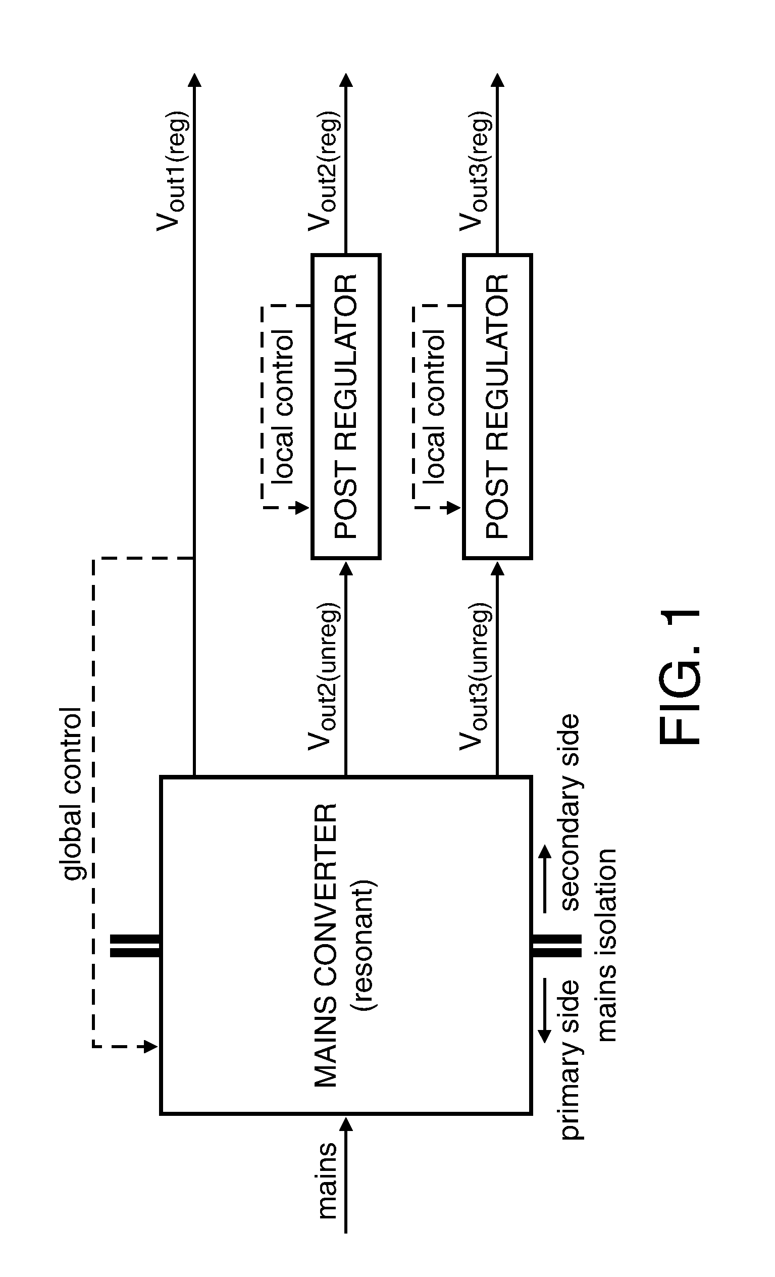
[0001]This application claims the priority under 35 U.S.C. §119 of European patent application no. 10162482.3, filed on May 11, 2010, the contents of which are incorporated by reference herein.FIELD OF THE INVENTION[0002]The invention relates to a power converter and to a method adapted to power conversion.BACKGROUND OF THE INVENTION[0003]Power converters are very much used in many applications for supplying a DC current or voltage to a consumer. There are applications in which multiple outputs are necessary for delivery of different voltages / currents in the same application.[0004]An example of state of the art power converter is shown in FIG. 1. State-of-the converters apply so-called post-regulation to generate auxiliary output voltages from one or more unregulated levels generated by the power converter. As an example, a resonant power converter is shown in FIG. 1. The rectified mains (50-60 Hz) or a DC voltage is supplied to the mains of the resonant converter. A global control ...

Claims


Application Information

Patent Timeline
Patent Type & Authority Applications(United States)
IPC IPC(8): H02M7/5383
CPCY02B70/1433H02M3/33561Y02B70/10
Inventor SMEETS, PATRICK EMANUEL GERARDUSSHRESTHA, RAMESWORNOWAK, KATARZYNAPANSIER, FRANSHALBERSTADT, HANSHOOGZAAD, GIAN
Owner NXP BV
Learn More