
Cycle decomposition analysis for remote machine monitoring

a technology of cycle decomposition analysis and remote machine monitoring, which is applied in the direction of testing/monitoring control systems, process and machine control, etc., can solve the problems of increasing production and cost, affecting production and cost, and requiring maintenance to maintain machine uptime, so as to reduce unplanned downtime and reduce downtime

Active Publication Date: 2011-11-17
JOY GLOBAL SURFACE MINING INC
View PDF3 Cites 43 Cited by
  • Summary
  • Abstract
  • Description
  • Claims
  • Application Information

AI Technical Summary

Benefits of technology

[0006]What is needed is a system for capturing information related to machine problems that allows the information to be accessible to remote maintenance staff. What is also needed is the ability to provide users of the machine with real-time information, data, trending and analysis tools to rapidly identify a cause of a machine problem in order to reduce unplanned downtime. What is further needed is the ability to provide remote maintenance staff access to the machine in order to solve the machine problem remotely, thereby reducing downtime associated with diagnosing faults.
[0007]In certain embodiments, the disclosed systems and methods increase the efficiency and operability of a machine by remotely collecting and analyzing machine data, and then predicting events and faults before they occur in order to prevent failures. The data is further reviewed to identify issues that require attention, allowing for streamlined analysis and workflow processes. The information is used to more accurately predict the actual time of planned maintenances, reduce unnecessary maintenances, and increase machine availability. The information is also used to identify design improvement opportunities to increase the machine's performance and quality. The information, which includes machine health and performance data, can further be used to avert machine breakdowns, target and predict maintenance actions, and improve machine uptime and cost per unit. The information facilitates improved surveillance of the machine, accelerates response to breakdowns, reduces the need for unscheduled maintenance, helps improve operating practices, proactively detects failures in time to prevent cascade damage, captures expertise of qualified personnel, provides real time feedback to enhance operator skill and performance, and enables best practices and significantly extends machine life that may reduce mean time to repair (MTTR), increase uptime, reduce operations costs, reduce maintenance costs, reduce warranty claims, improve mean time between failure (MTBF), improve mean time to shutdown (MTTS), improve productivity, improve utilization, improve responsiveness to faults, and improve parts lead time.

Problems solved by technology

It is well known that heavy duty industrial machinery requires maintenance to maintain machine uptime.
As machines increase in size, complexity, and cost, failure to maintain the machines results in greater impact to production and cost.
Information on why a machine failed is often not captured, thereby making it difficult to identify and troubleshoot any problems that led to the failure.
Furthermore, even if the information is captured, it is usually stored onboard the machine, making it inaccessible to remote maintenance staff, thereby hindering root cause analysis and condition-based maintenance initiatives.
Thus, while machine maintenance systems according to the prior art provide a number of advantageous features, they nevertheless have certain limitations.

Method used


Image

  • Cycle decomposition analysis for remote machine monitoring
  • Cycle decomposition analysis for remote machine monitoring
  • Cycle decomposition analysis for remote machine monitoring

Examples


Embodiment Construction

[0042]While this invention is susceptible of embodiments in many different forms, there is shown in the drawings and will herein be described in detail preferred embodiments of the invention with the understanding that the present disclosure is to be considered as an exemplification of the principles of the invention and is not intended to limit the broad aspect of the invention to the embodiments illustrated. Additionally, in the following detailed description, numerous specific details are set forth to provide a full understanding of the present disclosure. It will be obvious, however, to one ordinarily skilled in the art that the embodiments of the present disclosure may be practiced without some of these specific details. In other instances, well-known structures and techniques have not been shown in detail not to obscure the disclosure.

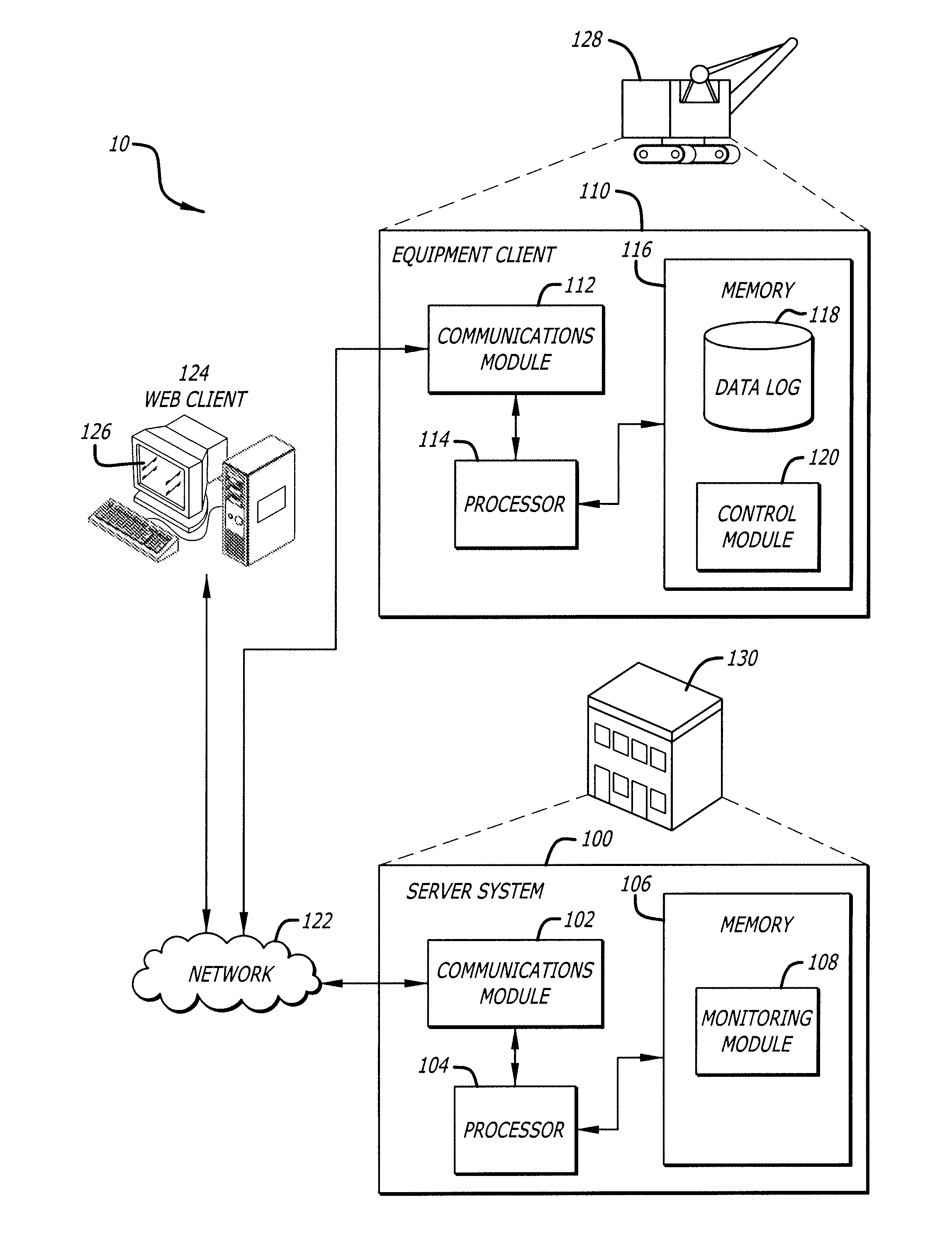
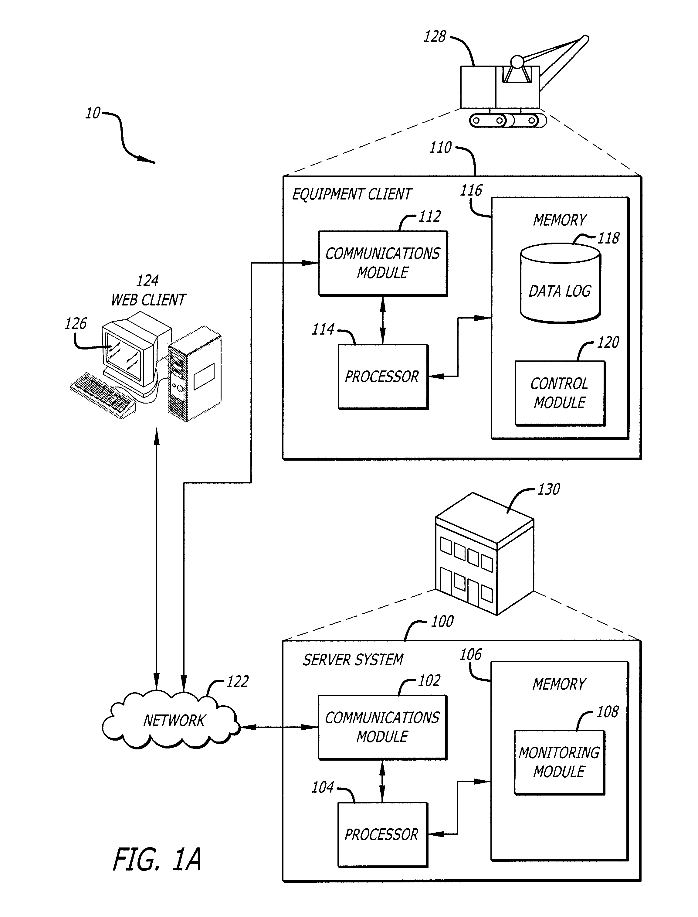
[0043]Referring now to the Figures, and specifically to FIG. 1, there is shown an architecture 10 that includes a system 10 for remotely monitor...


PUM


Abstract

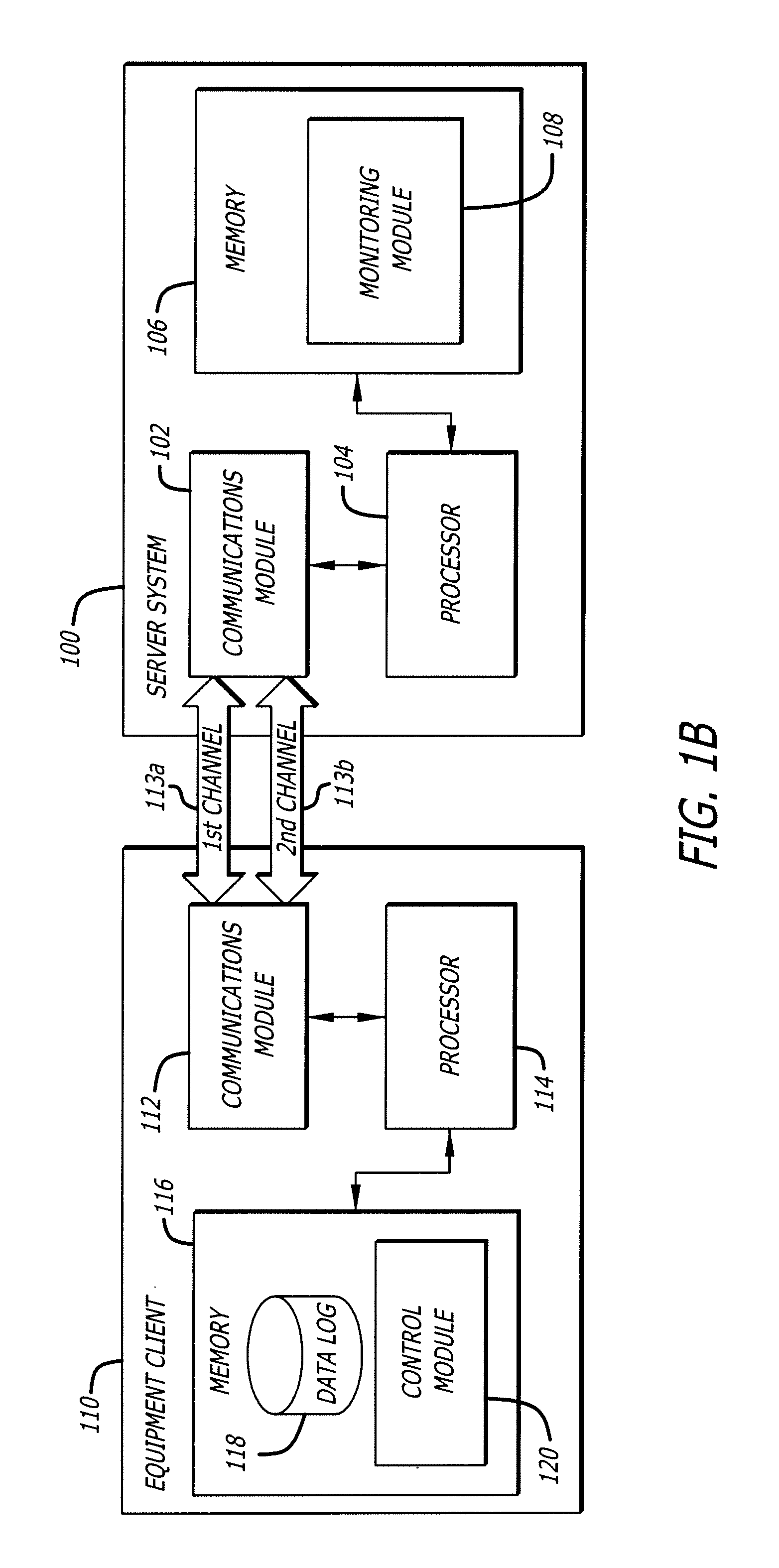
Methods for decomposing event information for a machine are described. In one aspect, a method includes receiving event data identifying events associated with a machine on a first communications channel, and receiving trend data for the machine associated with the identified events on a second communications channel separate from the first communications channel. Systems and machine-readable media are also described.

Description

CROSS-REFERENCE TO RELATED APPLICATIONS[0001]The present application claims the benefit of priority under 35 U.S.C. §119 from U.S. Provisional Patent Application Ser. No. 61 / 334,657 entitled “Remote Monitoring of Equipment,” filed on May 14, 2010, the disclosure of which is hereby incorporated by reference in its entirety for all purposes and made a part hereof.FEDERALLY SPONSORED RESEARCH OR DEVELOPMENT[0002]Not applicable.TECHNICAL FIELD[0003]The present disclosure generally relates to equipment monitoring, and specifically, to remotely monitoring heavy duty machinery.DESCRIPTION OF THE RELATED ART[0004]It is well known that heavy duty industrial machinery requires maintenance to maintain machine uptime. As machines increase in size, complexity, and cost, failure to maintain the machines results in greater impact to production and cost. Information on why a machine failed is often not captured, thereby making it difficult to identify and troubleshoot any problems that led to the f...

Claims


Application Information

Patent Timeline
IPC IPC(8): G06F17/18
CPCG05B23/0232G06K9/0014G06F21/554G05B23/02G06V20/695
Inventor RIKKOLA, MICHAELDANIEL, DONALDDANIEL, KENNETH
Owner JOY GLOBAL SURFACE MINING INC
Learn More