Eureka AIR delivers breakthrough ideas for toughest innovation challenges, trusted by R&D personnel around the world.

Rapid replacing system for air pre-filtering device

A pre-filtering and air intake system technology, applied in the field of air intake system, can solve the problems of shorter filter life than the design expected life, increase the number and cost of unplanned downtime to replace the filter screen, and heavy replacement workload, etc. Reliability and economy, reduction of unplanned downtime, excellent working conditions

Pending Publication Date: 2019-06-28
南京国源电气有限公司
View PDF0 Cites 3 Cited by
  • Summary
  • Abstract
  • Description
  • Claims
  • Application Information

AI Technical Summary

Problems solved by technology

[0002] The intake system provides clean air for turbomachinery such as gas turbines and industrial compressors through filtration and dehumidification to ensure its efficient, safe and reliable operation. The intake system is designed according to the specific ambient air quality, but the actual operation The ambient air quality is ever-changing under the conditions, and it is normal to deviate from the design conditions, which leads to the filter life of the intake system being shorter than the expected life of the design, requiring frequent replacement of filter elements, increasing the frequency and cost of unplanned shutdowns to replace filter screens, and replacing filter elements requires Operating in the intake room, there is a lot of flying dust and the working environment is harsh. At the same time, due to the large volume of the intake system of large gas turbines and industrial compressors, the replacement workload is heavy. , the replacement cycle of the filter screen is shorter during the period of high pollen occurrence, which has a greater impact on the safe, reliable and economical operation of the turbine machinery. Therefore, it is necessary to develop a pre-filter device that can be replaced online outdoors

Method used


Image

  • Rapid replacing system for air pre-filtering device
  • Rapid replacing system for air pre-filtering device
  • Rapid replacing system for air pre-filtering device

Examples


Embodiment 1

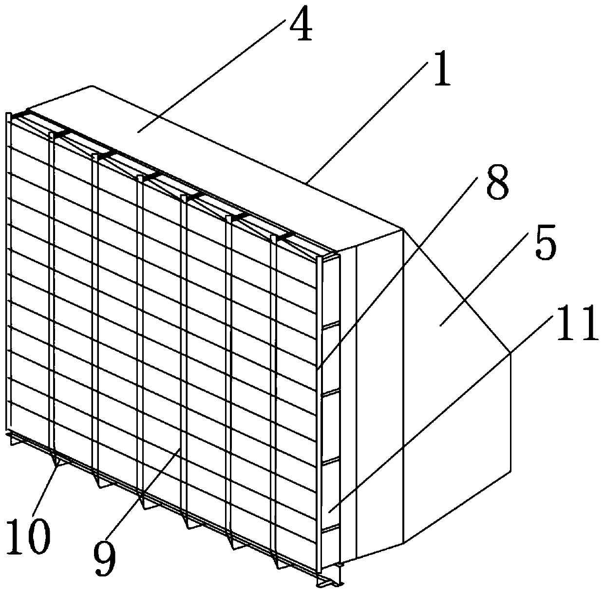
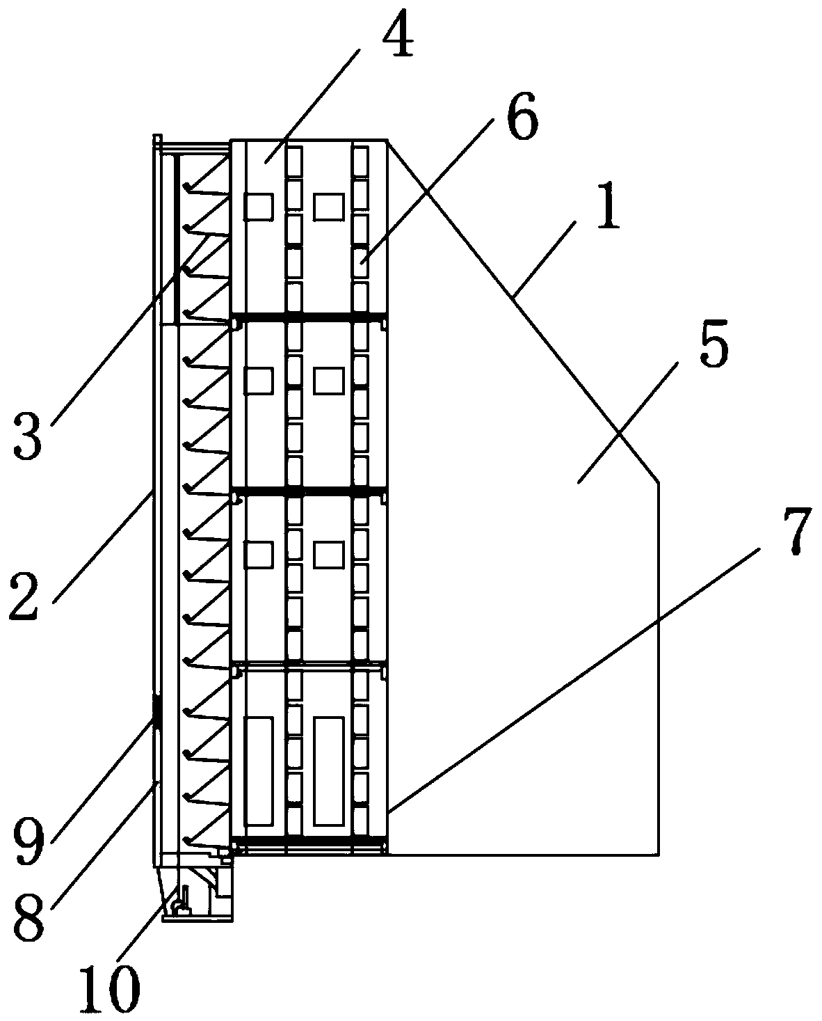
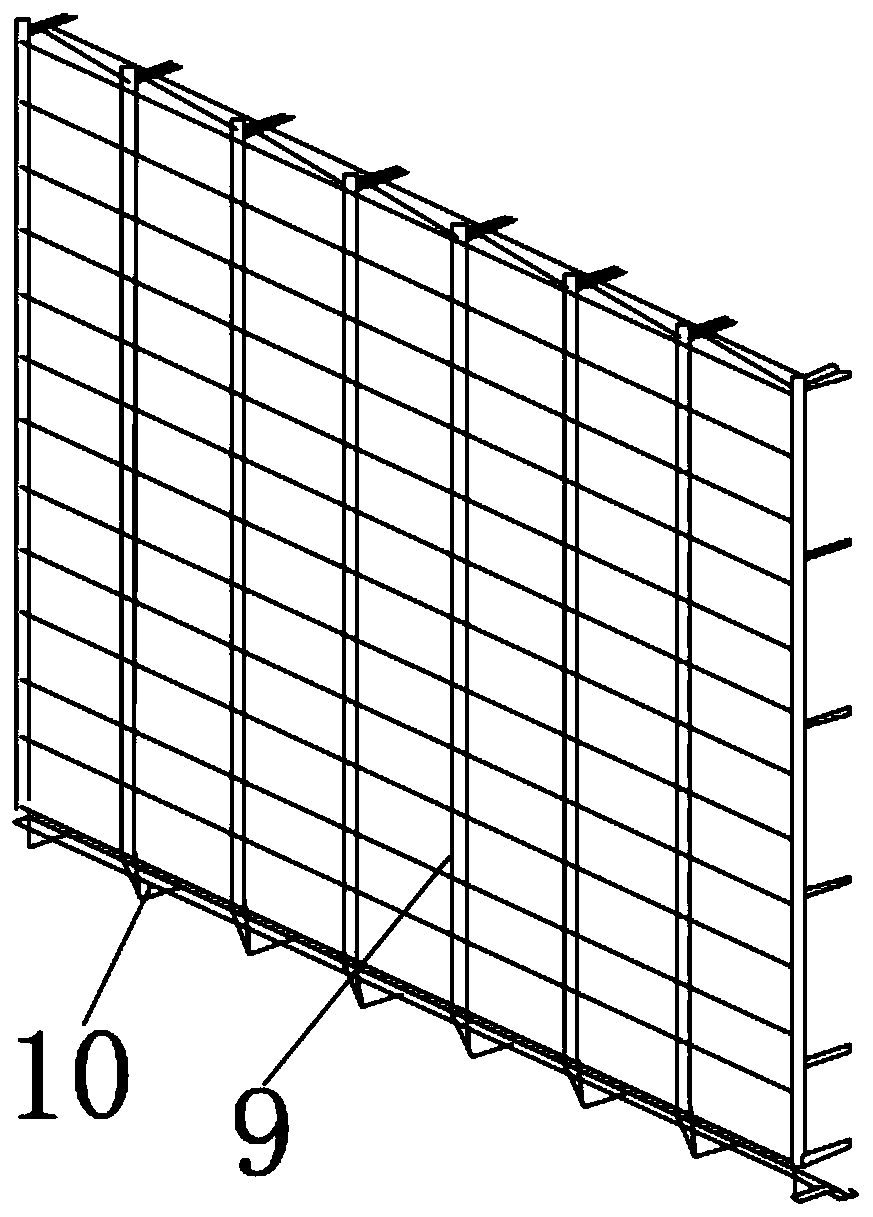
[0029] Such as Figure 1-11 As shown, the embodiment of the present invention provides a quick replacement system for an air pre-filter device. The pre-filter device 2 is installed on the air inlet side of the air intake system 1, and the air enters from the pre-filter device 2, and then passes through the rain-proof The cover 3 enters the filter chamber 4 and is filtered by the main filter element 6, then flows into the clean room 5, and then enters the compressor of the gas turbine. The pre-filter device 2 is connected to the intake frame 7 of the intake system 1 through a series of bottom cantilever beams 15, and the main cantilever beam 16. The support assembly 8 is used to fix and guide the pre-filter module 9 and the lifting mechanism 10 . The supporting assembly 8 is composed of a bottom beam 12, a plurality of bottom cantilever beams 15, several cross bars 14, vertical bars 13, a plurality of main cantilever beams 16, a top beam 17, a top hanger 18 and a bottom bracke...

Embodiment 2

[0031] Such as Figure 1-11 As shown, the embodiment of the present invention provides a quick replacement system for an air pre-filter device, the bottom beam 12 and the bottom cantilever beam 15 are U-shaped aluminum profiles, the vertical rod 13 is an H-shaped aluminum profile with positioning grooves on the surface, and the main cantilever The beam 16 and the top beam 17 are square tubes; the top hanger 18 and the bottom bracket 19 are channel steel. The crossbar 14 is a rectangular aluminum profile, the joints between the bottom crossbeam 12, the vertical pole 13 and the bottom cantilever beam 15 are connected by bolts, and the joints between the crossbar 14, the vertical pole 13 and the main cantilever beam 16 are bolted Connection; Bolt connection between the bottom cantilever beam 15 and the intake frame 7 of the intake system 1 .

Embodiment 3

[0033] Such as Figure 1-11 As shown, the embodiment of the present invention provides a quick replacement system for an air pre-filter device. The vertical pole 13 of the support assembly 8 divides the air intake surface into multiple vertical planes in the transverse direction, and the vertical plane between two adjacent vertical poles 13 is installed A set of lifting mechanism 10 and a pre-filter module 9 are provided. Side sealing plates are installed between the left and right ends of the support assembly 8 and the wall of the air intake system 1, thus forming a complete air pre-filter. The pre-filter element 21 can be installed in the Sliding up and down between the two adjacent poles 13 of the support assembly 8, by starting the hoist 30 of the lifting mechanism 10, the pre-filter modules 9 can be put into operation one by one, or the pre-filter modules 9 can be delisted to the ground or roof without Take scaffolding or other mobile lifting devices; in addition, between...


PUM


Abstract

The invention provides a rapid replacing system for an air pre-filtering device, and relates to the technical field of air inlet systems of gas turbines and industrial compressors. The rapid replacingsystem comprises a pre-filtering device, wherein a pre-filtering module is arranged on the surface of the pre-filtering device, a supporting component is embedded in the bottom of the side surface ofthe pre-filtering device, and a lifting mechanism is arranged at the bottom surface of the pre-filtering device. The pre-filtering element can be quickly replaced on line without stopping; the replacement is simple, the labor intensity is low, the operation environment is excellent, and no additional tool or fixture is needed; and the pre-filtering element shares the filtering burden of a downstream filter, prolongs the service life of the downstream filter with high purchase cost, reduces the frequency of unplanned stoppage, and improves the reliability and economical efficiency of machine operation.

Description

technical field [0001] The invention relates to the technical field of air intake systems of gas turbines and industrial compressors, in particular to a quick replacement system for air pre-filtering devices. Background technique [0002] The air intake system provides clean air for turbomachinery such as gas turbines and industrial compressors through filtration and dehumidification to ensure its efficient, safe and reliable operation. The air intake system is designed according to the specific ambient air quality, but the actual operation The ambient air quality is ever-changing under the conditions, and it is normal to deviate from the design conditions, which leads to the filter life of the air intake system being shorter than the expected life of the design, requiring frequent replacement of filter elements, increasing the frequency and cost of unplanned shutdowns to replace filter screens, and replacing filter elements requires Operating in the intake room, there is a ...

Claims


Application Information

Patent Timeline
Patent Type & Authority Applications(China)
IPC IPC(8): F02C7/05F04B39/16B01D46/10B01D46/42
CPCY02A50/2351
Inventor 陈劼莫俊武蔡晓清曹康李波卢桂贤刘威许可
Owner 南京国源电气有限公司
Why Eureka
Eureka Blog
Learn More